22
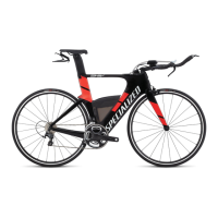
4. INSTALLING THE CABLE ROUTING COVER PLATE
E
F
TO BATTERY
6
Fig.6: Once the wiring or cable housing is routed, install the cable routing cover plate
E
, followed by the cover
plate bolt
F
(M6x15mm, 3mm countersunk Allen hex head). Apply grease to the bolt.
Fig.6: Torque the bolt to 25 in-lbf (2.8 Nm).
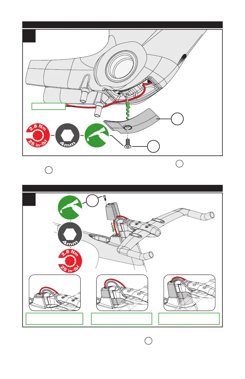
5. INSTALLING THE CABLE ROUTING CONTROL TOWER
7
SMALL TOWER, NO SPACER MEDIUM TOWER, 1 SPACER LARGE TOWER, 2 SPACERS
G
Fig.7: Once the bike fit has been finalized, choose the Control Tower that corresponds to the final amount of
spacers. Attach the Control Tower to the frame using the tower bolt
G
(M5x20mm, 4mm Allen hex head).
Apply grease to the bolt.
Fig.7: Torque the bolt to 25 in-lbf (2.8 Nm).