20
2. ROUTING THE DERAILLEUR CABLES / WIRES AT THE BOTTOM BRACKET
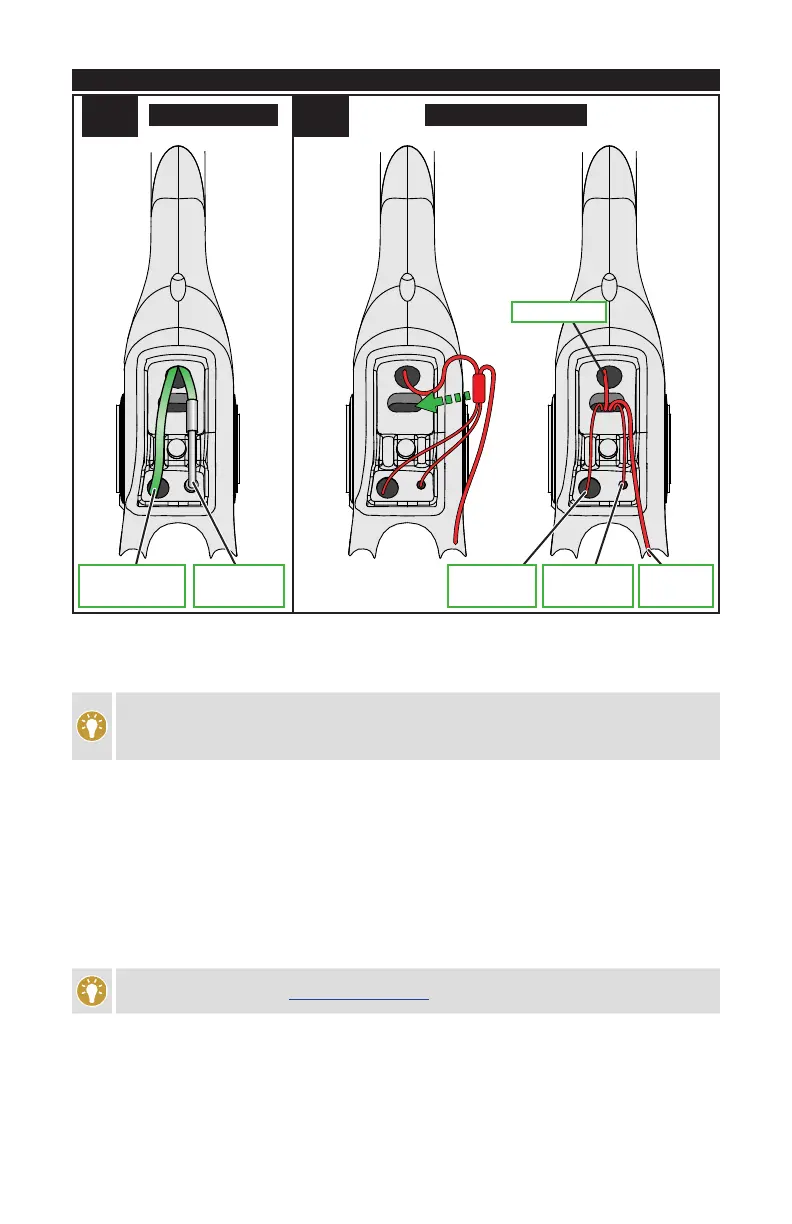
5-A 5-B
TO FRONT
DERAILLEUR
TO REAR
DERAILLEUR
TO
BATTERY
TO SHIFTERS
TO FRONT
DERAILLEUR
TO REAR
DERAILLEUR
CABLE SYSTEM ELECTRONIC SYSTEM
OPTION 5-A: STANDARD CABLE
Rear derailleur: Route the rear derailleur cable housing through the large hole going into the drive-side
chainstay.
To help guide the rear derailleur cable housing through the chainstay, run a gear cable through the
chainstay starting at the dropout and exiting at the bottom bracket cable guide port. This will help
guide the housing through the chainstay and out the dropout.
Front derailleur: Trim the front derailleur cable housing to the appropriate length to insert into the cable noodle,
then route the noodle into the non-drive-side hole going up toward the seat tube. This noodle acts as a cable
stop, the cable will be bare leading to the front derailleur.
OPTION 5-B: ELECTRONIC WIRING
Rear derailleur: Route the rear derailleur cable housing or wire through the dropout hole and out the large drive-
side hole at the bottom bracket.
Front derailleur: Route the wire through the hole in the seat tube and out the small non-drive-side hole at the
bottom bracket.
Join the connectors according to the manufacturer’s instructions, then place any excess wiring up into the frame
in front of the bottom bracket shell.
For Di2 instructions, refer to techdocs.shimano.com for Shimano guides.