Shure Incorporated
6/32
1.
2.
◦
◦
◦
3.
1.
Step 3: Listen and Adjust
Open the videoconferencing software on the computer connected to the ANIUSB-MATRIX. In the settings, choose the
ANIUSB-MATRIX as the speaker and microphone.
Place a test call with the whole system. Have the far-end caller tell you how the microphone signal sounds and make
adjustments as needed:
Microphone: [Your room] > MXA902 > IntelliMix
Loudspeaker: [Your room] > MXA902 > Loudspeaker > Speaker output.
ANIUSB-MATRIX: [Your room] > ANIUSB-MATRIX
If needed, move the microphone's coverage area: [Your room] > Coverage. You can also listen to the microphone
signal directly using a Dante headphone amp to help make adjustments.
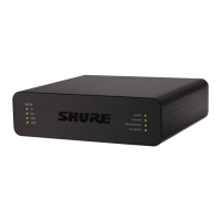
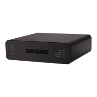
ANIUSB-MATRIX Parts
The LEDs on the front of the ANIUSB-MATRIX behave the same as the ones on the back of the device.
Sig/clip level indicators
Tricolor LEDs indicate the audio signal level for the analog channels and connectivity status for the USB channel. Ad
just output levels in Shure Designer software to avoid clipping.
Sig/Clip In and Out LED Behavior
LED State Audio Signal Level
Off Less than −60 dBFS
Green −59 dBFS to −24 dBFS
Yellow −23 dBFS to −1 dBFS
Red 0 dBFS or more
Note: The input and output LEDs are off when metering is set to post-gain.
USB Audio LED Behavior
LED State Meaning
Off No USB device connected
Green USB device operating successfully
 Loading...