Do you have a question about the Shure SLX2 and is the answer not in the manual?
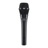
| Type | Presentation microphone |
|---|---|
| Microphone mute | Yes |
| Display type | LCD |
| Backlight color | Green |
| Product color | Black, Silver |
| Housing material | Acrylonitrile butadiene styrene (ABS) |
| Battery type | AA |
| Power source | Battery |
| Battery life (max) | 8 h |
| Number of batteries supported | 2 |
| Device interface | - |
| Operating frequency | 638 - 662 MHz |
| Connectivity technology | Wireless |
| Width | 51 mm |
|---|---|
| Height | 254 mm |
| Microphone weight | 290 g |
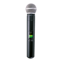
Describes the physical features of the SLX2 transmitter, including its display and controls.
Explains how to access and set the two available gain settings for vocal volume.
Details the process for manually selecting group and channel settings on the transmitter.
Explains how to lock or unlock transmitter settings to prevent accidental changes.
Describes the display indicator for remaining transmitter battery charge.
Explains the indicator that shows when a master list frequency is in use.
Details the warning indicator for mismatched transmitter and receiver frequencies.
Details the audio signal path, preamp, ARC processor, and compression stages.
Explains the battery power supply, boost converter, and power-on/off mechanisms.
Describes the software routine for shutting down the unit on low battery.
Explains the RF signal path, including VCO, PLL synthesizer, and RF power amplifier.
Details how to access different operating modes, including ATE Mode.
Explains the Automatic Test Equipment mode and its test frequencies.
Describes resistors that determine the RF band based on voltage.
Explains microcontroller decisions based on analog voltage inputs for battery status.
Lists necessary test equipment for performing functional tests.
Describes the initial listening test procedure for verifying normal operation.
Details the setup requirements for conducting functional tests.
Describes how to test the functionality of the transmitter's display.
Explains how to test the transmitter's reverse battery protection.
Details testing voltage regulation at specific points on the PCB.
Describes the procedure to measure the unit's current consumption.
Details the procedure for testing the audio frequency response.
Describes the procedure for measuring total harmonic distortion and noise.
Tests RF output power and frequency stability using a spectrum analyzer.
Details the procedure for testing the tone key level.
Describes occupied bandwidth testing specific to the JB model.
Details adjacent channel power testing specific to the JB model.
Provides a visual breakdown of the transmitter components for assembly/disassembly.
Explains audio level measurement references and dB conversions.
Lists the required test equipment for performing service procedures.
Outlines the sequential steps for alignment and measurement.
Details checking DC voltages at specific test points for regulation.
Describes the initial setup steps required before performing alignment.
Covers RF tuning procedures, specifically VCO tuning steps.
Details the procedure for aligning the transmitter's frequency.
Explains how to measure and adjust RF output power.
Details adjusting transmitter deviation for proper companding.
Recommends using an SLX4 receiver for deviation adjustment.
Details the setup of the SLX4 receiver for testing.
Explains how to establish a deviation reference voltage.
Describes measuring radiated deviation reference voltage.
Lists preprogrammed frequencies for the H5 band, organized by group.
Lists preprogrammed frequencies for the J3 band, organized by group.
Lists preprogrammed frequencies for the JB band, organized by group.
Lists preprogrammed frequencies for the L4 band, organized by group.
Lists preprogrammed frequencies for the P4 band, organized by group.
Lists preprogrammed frequencies for the Q4 band, organized by group.
Lists preprogrammed frequencies for the R5 band, organized by group.
Lists preprogrammed frequencies for the S6 band, organized by group.
Lists key performance specifications for the SLX2 transmitter.
Details specific changes and characteristics for the JB model.
Details the physical dimensions, weight, and housing.
Covers general specs like operating range, audio response, and impedance.
Specifies temperature conditions for storage and stabilization.
Details temperature cycling test requirements and stabilization.
Specifies operational temperature range and stabilization.
Details steady state humidity testing and evaluation.
Specifies operational humidity conditions and stabilization.
Details moisture resistance testing and recovery.
Describes mechanical shock testing, including drop tests.
Details electrostatic discharge testing requirements.
Initial tests to perform when troubleshooting a unit.
Troubleshooting steps for issues related to RF frequency or signal presence.
Troubleshooting steps for diagnosing low RF output power.
Troubleshooting steps for excessive current drain issues.
Troubleshooting steps for issues related to audio deviation.
Troubleshooting steps related to the microcontroller's operation.
Notes on product changes relevant to replacement parts.
Explains designations for resistors, capacitors, and other components.
Lists SLX2 model variations by country code, frequency range, and designation.
Lists hardware replacement parts with reference designations and part numbers.