8
25A1090 (Rev.3)
This table shows the variant resistor values and resulting voltages at TP_RFBAND for each
band.
Note: Voltages are calculated with a 3.30V (+/- 0.10V) reference from the power
supplies. If power section supports less than 3.30V, thresholds need to be adjusted.
µC DECISIONS BASED ON ANALOG VOLTAGES
Note: There is a dead battery lock voltage set at 2.30 Volts. If the transmitter is powered
on with a voltage of less than 2.30 Volts, the system will lock, forcing the user to either
recharge or replace the batteries. During the dead battery lock out, the battery gauge is
empty and the red led flashes.
RF BAND Rb TP_RFBAND(+/- 0.10V)
H5 1.00k 0.30V
J3 2.99k 0.76V
L4 4.99k 1.10V
R5 7.50k 1.41V
S6 12.10k 1.81V
P4 18.2k 2.13V
Q4 30.1k 2.48V
JB 49.9k 2.75V
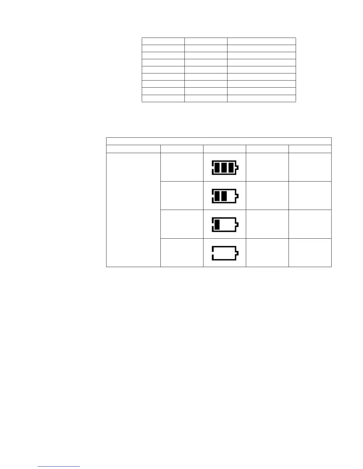
Continuous Operation Battery Thresholds
BATTERY_A2D RF Level Display Logic Voltage (V)
Measured @ 3V
block battery clips
- dBC >= 2.25
- dBC < 2.25
- dBC < 2.14
-8 dBC < 2.05