16
25A1090 (Rev.3)
RECEIVER SETUP
1. The SLX2 transmitter should be powered OFF for this procedure.
2. Connect the rf signal generator to any of the antenna inputs on the receiver. Make sure the
dc block is on the rf signal generator.
3. Set rf signal generator to the same frequency as the SLX2 transmitter.
4. Set rf signal generator modulation to 1 kHz and deviation to 33 kHz.
5. Set the amplitude of the rf signal generator to -50 dBm.
6. Disable tonekey by shorting the pads of R280 on the receiver.
DEVIATION REFERENCE LEVEL
1. Power ON the receiver.
2. Connect the unbalanced output of the SLX4 receiver to the audio analyzer input.
3. Note the voltage obtained. This is the deviation reference voltage.
4. Disconnect the rf signal generator from the SLX4.
5. Power OFF the receiver and remove the short on the R280 pads to enable tonekey.
RADIATED DEVIATION REFERENCE VOLTAGE
1. Connect the audio analyzer output to the Mic Test Head input of the transmitter.
2. Power ON the receiver.
3. Apply +3V to the battery terminals on the SLX2 and power up the unit.
4. Set the audio analyzer frequency to 1kHz.
5. Adjust the audio analyzer amplitude level (typically = -6.5 dBu) to obtain -13 dBu
± 0.1dB
at TPA1. (This corresponds to -9 dBu ± 2dB at the audio input (TPA0))
.
6. Adjust TR160 to obtain -3 dBu
± 0.15dB at TPA2.
7. Place the transmitter closer than 12 inches (36 cm) to the receiver.
8. Connect both antennas on the receiver.
9. Connect the un
balanced output of the receiver to the audio analyzer.
10.
Adjust TR200 until the ac voltmeter connected to the receiver unbalanced output reads the
same
deviation reference voltage
± 0.1dB, as measured above.
(TR200 adjusts the deviation for 33 kHz, 100% modulation.)
If successful in the alignment of the unit, assemble it back together as indicated on
page 12. If not successful refere to our Bench Checks section on page28.
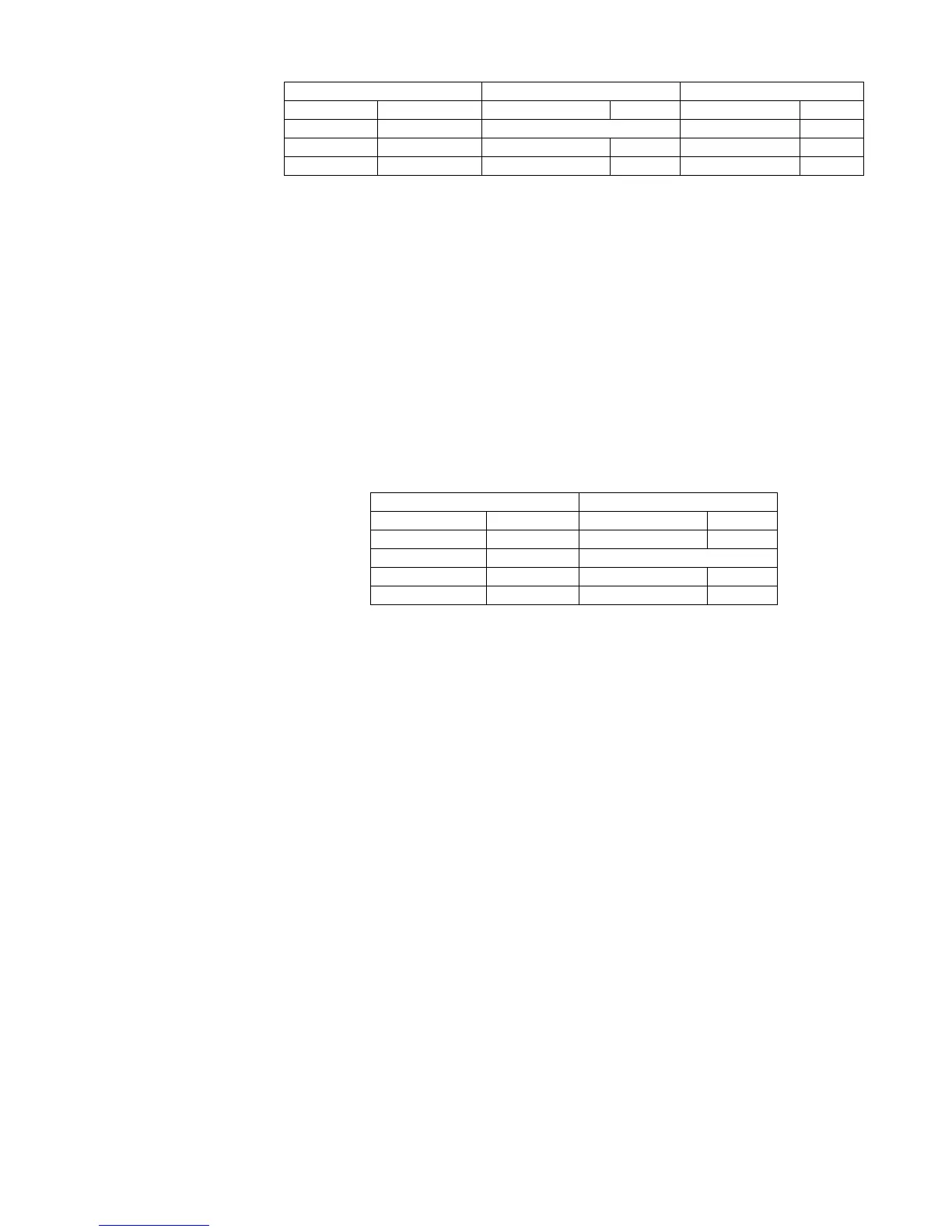
SLX4 RECEIVER AUDIO ANALYZER RF SIGNAL GENERATOR
Output: Unbalanced Measurement: AC level INT: FM
Gain: Maximum Filters: FM RATE: 1kHz
Toke Key: Disabled (R280) Low-Pass (30 kHz): ON Amplitude: -50 dBm
High-Pass (400 Hz): ON Deviation: 33 kHz
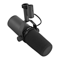
SLX2 TRANSMITTER AUDIO ANALYZER
Power: +3 Vdc Measurement: AC level
Atennuation: -10 dB Output: 1 kHz
Channel: See Table Filters:
Group: See Table Low-Pass (30 kHz): ON
High-Pass (400 Hz): ON