6
25A1090 (Rev.3)
with C600 - C604. The collector of Q600 feeds the power amplifier stage via an impedance
matching network consisting of L602, C611, and C618.
The bias voltage for the RF power amplifier (Q601) is supplied by R601 and R604. Its operat-
ing current is controlled via emitter resistor R606. RF choke L601 provides power and decoupling
for the stage, in conjunction with C605-C609. For Japanese systems only, the output power is
trimmed via TR640. L603, C612, and L604 provide the output impedance matching into the low
pass filter, which consists of L604, L605, L606, C615, C616, and C617. The low pass filter output
couples to the battery antenna via C641 and L607. Connector CON640 and C613 are only used
for Japanese (JB) units. Coupling capacitor C610 is used to ensure that both batteries are driven
equally.
The transmitter is capable of delivering up to +15.0 dBm to the antenna (depending
on band and country). During transmitter power-up and frequency selection, the RF
output is muted by bringing the base of Q631 low, which removes bias from Q630
and shuts down power to the RF stages. The RF output is also muted during the
transmitter power-down sequence. This is done so that the carrier signal will not
interfere with other transmissions when the loop becomes unlocked.
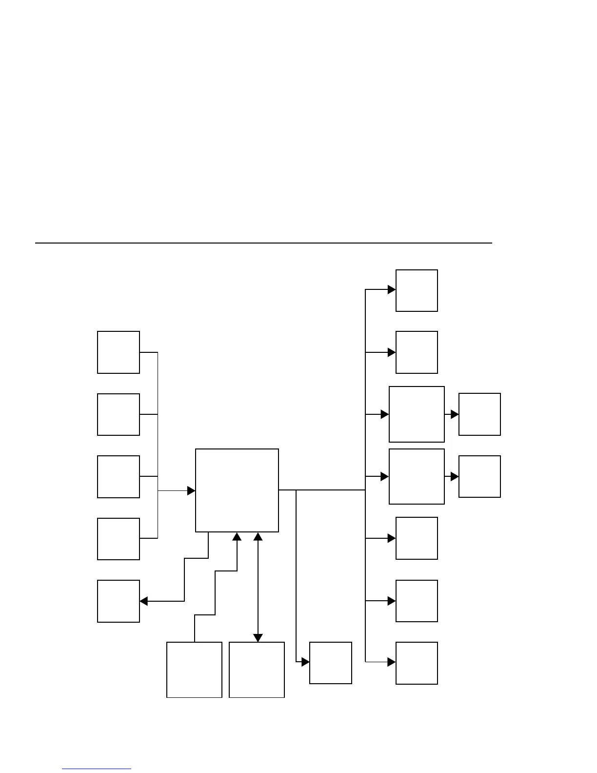
DIGITAL CIRCUIT DIAGRAM
RF Band
DC Level
Battery DC
Level
Power Mute
Button
Select
Button
Softstart
Shutdown
Infrared
Photodetector
(Sharp GP1U10X)
EEPROM
(MicroChip
93AA46 )
Microprocessor
(Motorola
MC68HC908GR16)
Backlight
LED
Power LED
LCD
VCO
RF Power
Tonekey
Squarewave
Tonekey
Level
LCD Driver
(Rohm
BU9729k)
Sythesizer
(National
Semiconducter
LMX2335)
Audio Mute