10
25A1090 (Rev.3)
FUNCTIONAL TEST
REQUIRED TEST EQUIPMENT (OR APPROVED EQUIVALENT OR SUPERIOR MODELS):
LISTENING TEST
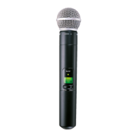
Before completely disassembling the transmitter, operate it to determine wether it is functioning normal-
ly and try to duplicate the reported malfunction. Refer to pages 2 and 3 for operating instructions, trouble-
shooting, and specifications.
Review any customer complaint or request, and focus the listening test on any reported problem. The
following, more extensive, functional tests require partial disassembly.
FUNCTIONAL TEST
Refer to the Disassembly section to partially disassemble the transmitter for the following functional
tests.
TEST SETUP
1. Remove the PCB from the handle.
2. Set gain switch to “0” dB.
3. Connect the (+) terminal of the power supply through a milliammeter to the (+) battery terminal and
the (-) power supply terminal to the (-) battery terminal.
4. Connect a DC Voltmeter across the power supply and set the power supply for 3Vdc.
5. Connect the audio analyzer to the microphone via the microphone test head (PT1840) as needed.
DISPLAY TEST
1. Power unit ON.
2. Verify that all display segments are displayed for approximately 2 seconds. This includes a full bat-
tery indication and "1818" displayed for group and channel.
REVERSE BATTERY PROTECTION TEST
1. Adjust power supply to -3.0 ± 0.1 V dc.
2. The current should be less than 0.5 mA.
VOLTAGE REGULATION TEST
With power applied properly, and the unit switched on, measure the DC voltages at the following test
points. All test points are located on the top side of the PCB. Refere to the component diagram.
• TPBATT+ (Battery input) = 3 ± 0.2 Volts
• TP5V (Power Converter) = 5 ± 0.2 Volts
• TP3.3V (Power Converter) = 3.3 ± 0.2 Volts
• TPA1 (Audio Preamp) = 2.5 ± 0.2 Volts
• TPA3 (Tone Key Summing Amp (IC150 Pin 14)) = 2.5 ± 0.2 Volts
• TPVREF (IC100 Pin 5) = 2.5 ± 0.1 Volts
CURRENT CONSUMPTION TEST
1. With +3V applied to the battery terminals and the unit powered on.
2. Verify the current drain is 130 ± 15mA.
Spectrum analyzer or power meter HP8590L/Agilent E4403B/Agilent E4407B
Digital multimeter Fluke 87
Audio Analyzer HP 8903B
Frequency Counter HP 53181/HP 5385A
Power Supply Power Supply must be able to supply 3Vdc
with an internal ammeter.
Shielded test lead Shure PT1838F
BNC (Male) to BNC (Male) cable (1) Shure PT1838A
UA820 Antenna Frequency Dependent
Audio Test Head PT1840
Brass Ring PT1838Y