7
25A1090 (Rev.3)
DIGITAL SECTION
ACCESSING DIFFERENT MODES
ATE MODE
If TP_PB0 is held to TP_EGND, or logic level 0, at startup, the microcontroller will enter ATE
Mode. To ensure proper operation, TP_PA0 and TP_PA1 should be held to TP_EGND at startup.
In ATE Mode, each band has a three test frequencies that are controlled by the logic levels at
test points TP_PA0 and TP_PA1.
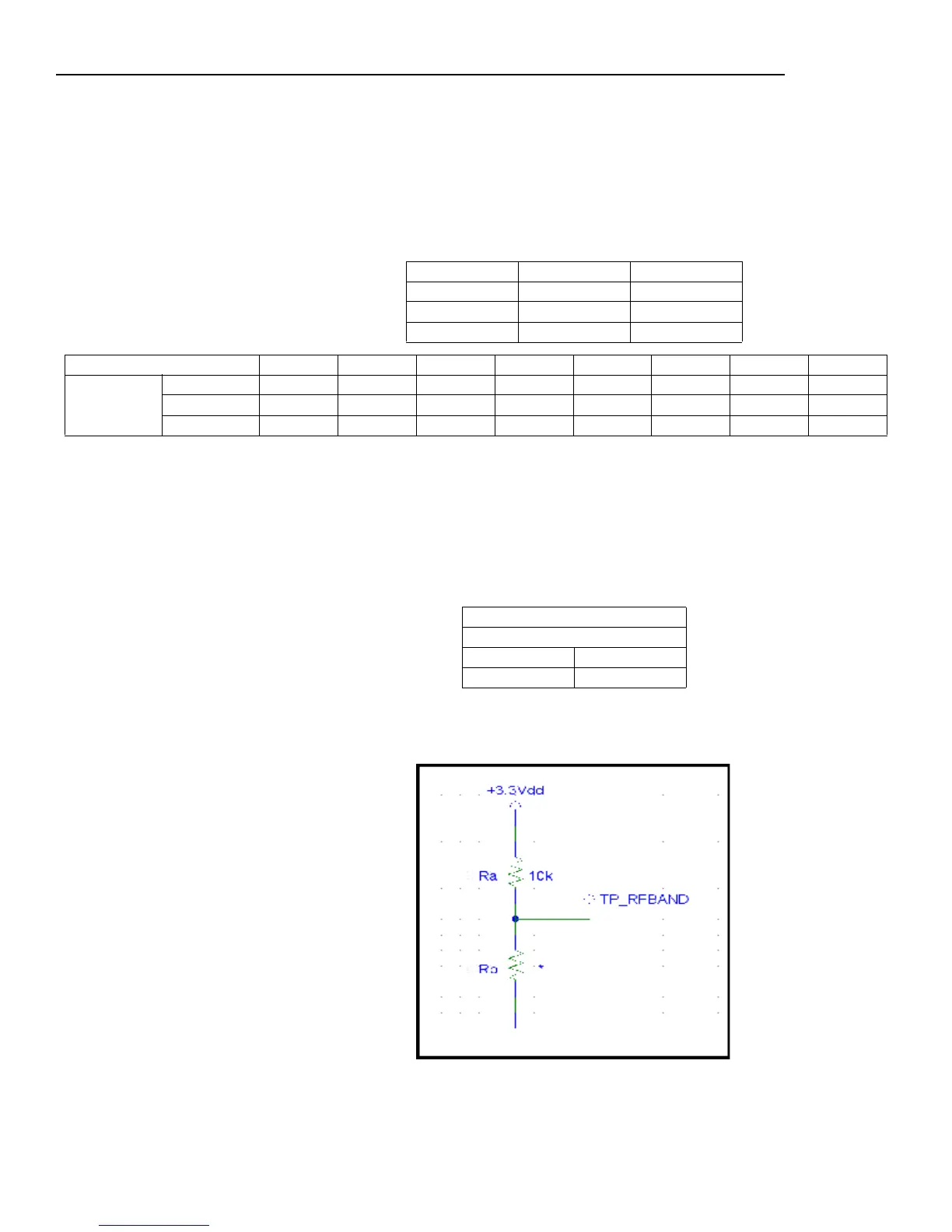
RF BAND RESISTORS
Two resistors (R
A
and R
B
) are responsible to start the microcontroller in a RF band. They de-
termine the voltage at test point TP_RFBAND.
This table shows R
A
's and R
B
's reference designators and how the voltages at the test points
reflect the operating RF band.
This figure depicts the voltage divider feeding the microprocessor analog to digital converter.
.
Frequency TP_PA0 TP_PA1
Low 00
Center 01
High 11
Test Frequencies (MHz) H5 J3 JB L4 P4 Q4 R5 S6
SLX2 Low 518.400 572.400 806.125 638.400 702.100 740.125 800.525 838.100
Center 529.500 583.500 807.500 649.500 714.000 746.325 810.275 851.300
High 541.800 595.800 809.750 661.800 725.900 751.875 819.800 864.800
SLX Reference Designators
SLX2
R
A
R
B
R319 R320