J6
J7
BLA CK OR B ROWN
WHI TE OR ORA NGE
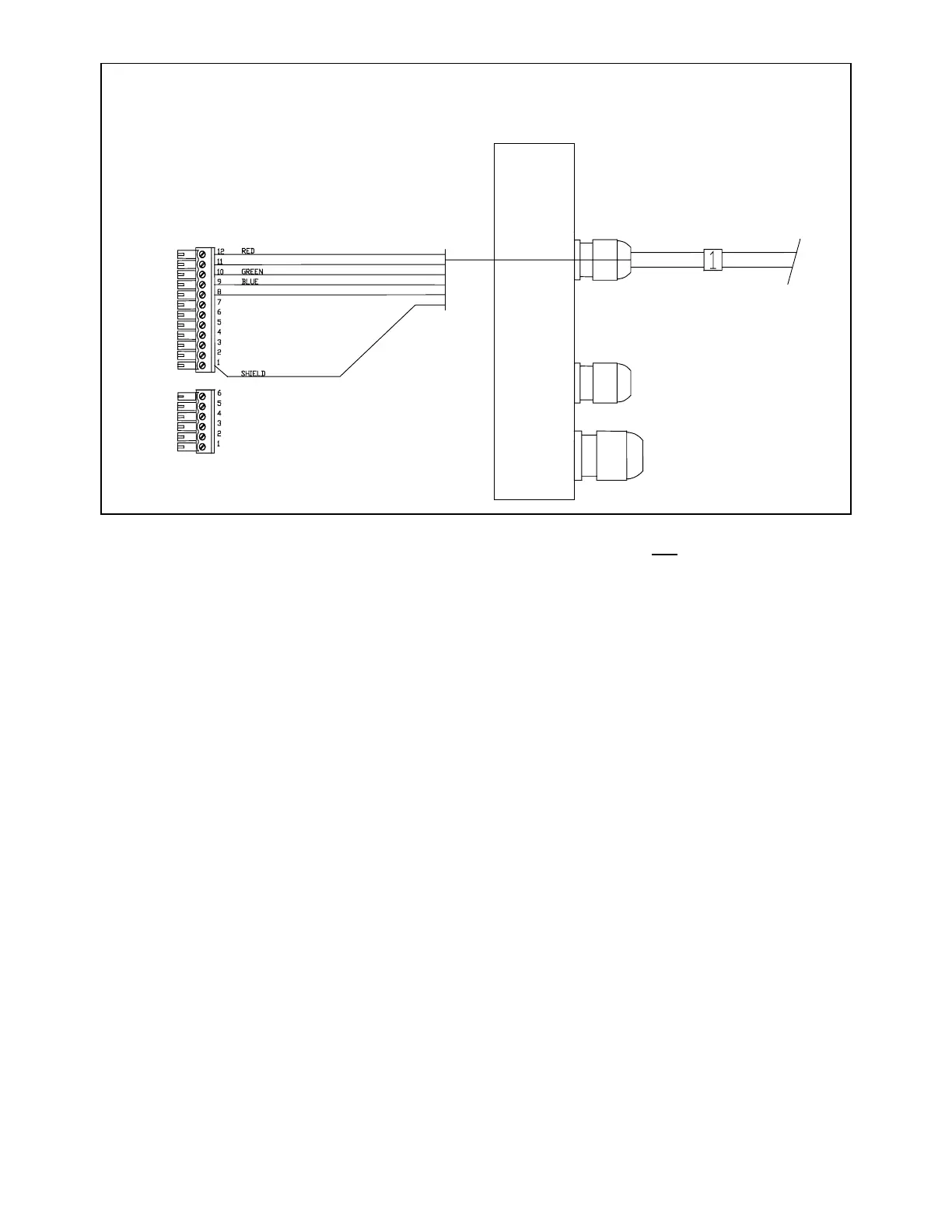
Right-hand side. Cable 1, Control Unit
Note: There is an extra yellow wire in the cable that is not used.
Pull all of the terminal strips from the right-hand end of the Processor.
Note that there is an empty socket which does not have a terminal strip. When you replace the
terminal strips, do not accidentally place one into the empty socket.
Pass the wires numbered "1", "2" and "3" through the watertight glands on the right end cap as
shown in the diagrams labelled:
• Right-Hand Side. Cable 1, Controller
• Right-Hand Side. Cable 2, Compass
• Right-Hand Side. Cable 3, Rudder Feedback
Use the same diagrams to wire the individual wires to the terminal strips.
Insert the bared end of the wire into the terminal strip and fasten it there by tightening the screw on
the terminal strip. Start from one end of the terminal strip and work to the other in sequence. Check
your work.
 Loading...