80 User Manual S60
ExceptforabriefperiodduringtheinitialtestcycleforallthreeLEDs,thegreenand
redLEDsareneverlitsimultaneously.
CHARGING THE POWER SUPPLY BATTERY
Perform the following operations to completely recharge the battery:
1.Pluginthebatterychargertothe220Vmainssocket
2.Insertthebipolarplugconnectorinthesocketplacedonthesideofthelevercontrol
3.Waitforthebatterytobechargedwiththeconnectedbatterycharger(4/5hours
if completely flat)
4. Disconnect the battery charger from the mains and from the control lever.
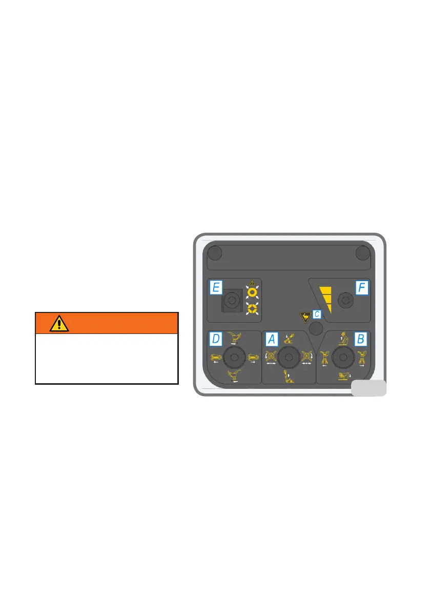
DESCRIPTION OF CONTROL LEVER
CONTROLS (CONTROL ARM)
Four-position joystick (A fig. 13)
With horizontal movement it controls
turntable spindle holder structure
clockwise and counter clockwise
rotation.
With vertical movement it controls
theupward/downwardmovementof
the tool arm.
Four-position joystick (B fig. 13)
Withhorizontalmovementitcontrolsthetoolcarriageright/lefttransfer.Withvertical
movementitcontrolsturntablespindleholderarmupstroke/downstroke.
On/offbutton(Cg.13)
If pressed together with the turntable spindle holder structure transfer, or with the
tool carriage transfer, it activates the high speed transfer control. The transfer high
speed control must be used only in the approaching steps. During the high speed ap-
proaching steps the turntable spindle rotation control is disabled for safety reasons.
Four-position joystick (D fig. 13)
With the vertical movement it drives the tool unit clockwise and counter clockwise
rotation.
Withhorizontalmovementitcontrolsturntablespindleholderstructureright/lefttransfer.
Three-position lever (central zero) (E fig. 13)
13
insist onto the control to make
sure the two arm blocking rat-
chets are completely hooked in
the working position (fig. 13)
CAUTION!