User Manual S60 81
UK
With vertical movement it controls the
opening and closing of turntable spindle.
Three-position lever (F fig. 13)
It adjusts the turntable spindle speed.
With lever in maximum speed position the
turntablewillrotateat10rpm.
With lever in intermediate speed position
theturntablewillrotateat6rpm.
With lever in minimum speed position the
turntable will rotate at 4 rpm.
With lever in minimum speed position, it is possible to further reduce the revolutions
per minute to obtain the optimal speed for the tread design. This further speed re-
duction, occurs only by rotating the turntable clockwise.
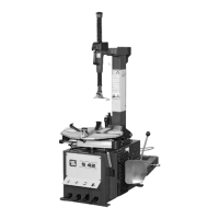
StopBUTTON(Hg.14)
Press the stop button to stop all machine signals.
To restore the controls simply reset the stop button. Wait for a few seconds for the
automatic restoring of the signal communication before giving any other command.
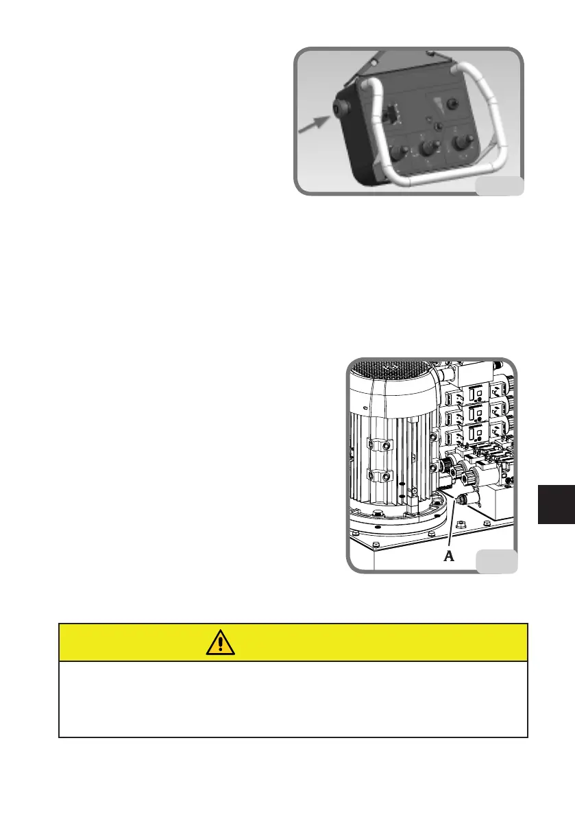
WHEEL LOCKING
OPERATION
The machine has a high pressure hydraulic circuit
for the movements.
The pressure in this circuit can be adjusted by
turningtherelativescrew(Ag.15),shownbelow.
S60
pressureadjustmentrange:from80to180bar
normaloperatingpressure:180bar
The pressure at which the machine is set can be
checked on the pressure gauge (C, Fig. 11) by
operating the turntable open control to its end of
stroke or by locking a rim.
WARNING
When working with light alloy rims, it's a good idea to use the specific clamps (sup-
plied on request) (fig.15a) to avoid scratching or scuffing the rim itself. To prevent the
rim from rotating on the clamps, a pin for alloy wheels must be inserted in one of the
rim fixing holes (A fig.15b).
15
14
 Loading...