Electro-
optical
signal
isolator
Electro-
optical
signal
isolator
Power
Supply
SICK
Device
1 2 2 43
6 5
System
Controller
= 7
= 8
= 9
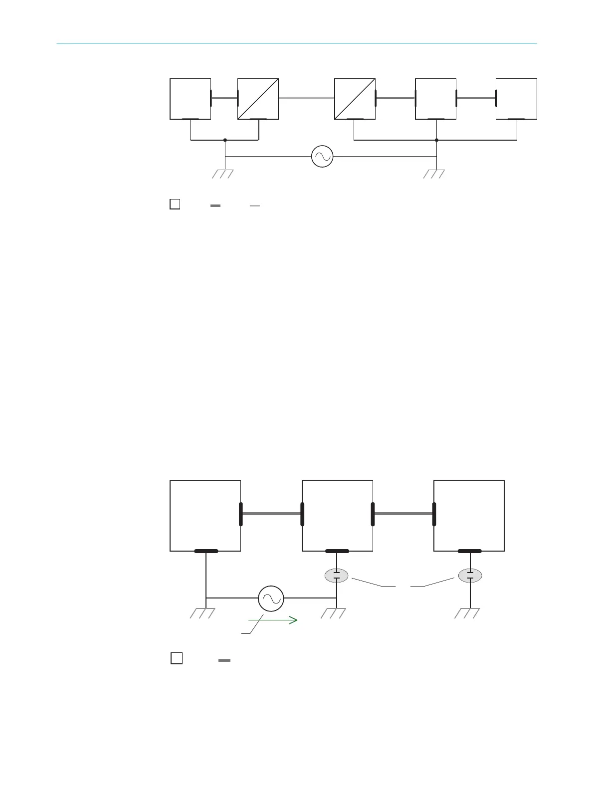
Figure 17: Example: Prevention of equipotential bonding currents in the system configuration by
the use of electro-optical signal isolators
1
System controller
2
Electro-optical signal isolator
3
Device
4
Voltage supply
5
Grounding point 2
6
Grounding point 1
7
Metal housing
8
Shielded electrical cable
9
Optical fiber
The use of electro-optical signal isolators between the islands isolates the ground loop.
Within the islands, a stable equipotential bonding prevents equalizing currents on the
cable shields.
Measures for small system installations
For smaller installations with only slight potential differences, insulated mounting of the
device and peripheral devices may be an adequate solution.
U
System
Controller
Power Supply
SICK
Device
8 6
5
21 3
4
7
= 9
= ß
Figure 18: Example: Prevention of equipotential bonding currents in the system configuration by
the insulated mounting of the device
1
System controller
2
Device
3
Voltage supply
ELECTRICAL INSTALLATION 6
8022502/15NT/2020-02-11 | SICK O P E R A T I N G I N S T R U C T I O N S | Lector621
35
Subject to change without notice