Characteristic data of the digital outputs
Table 54: Characteristic data of the digital outputs “External output 1” and “External output 2”
Type Switching
Switching behavior PNP switching to supply voltage V
S
Default settings in the device: no function, logic: not inverted (active
high)
Properties
•
Short-circuit protected + temperature protected
•
Not electrically isolated from V
S
Electrical values 0 V ≤ V
out
1)
≤ V
S
(V
S
− 1.5 V) ≤ V
out
≤ V
S
at I
out
2)
≤ 100 mA
1)
Output voltage
2)
Output current
NOTE
Assign the functions for the external digital outputs in the device using a configuration
tool, e.g., the SOPAS ET configuration software.
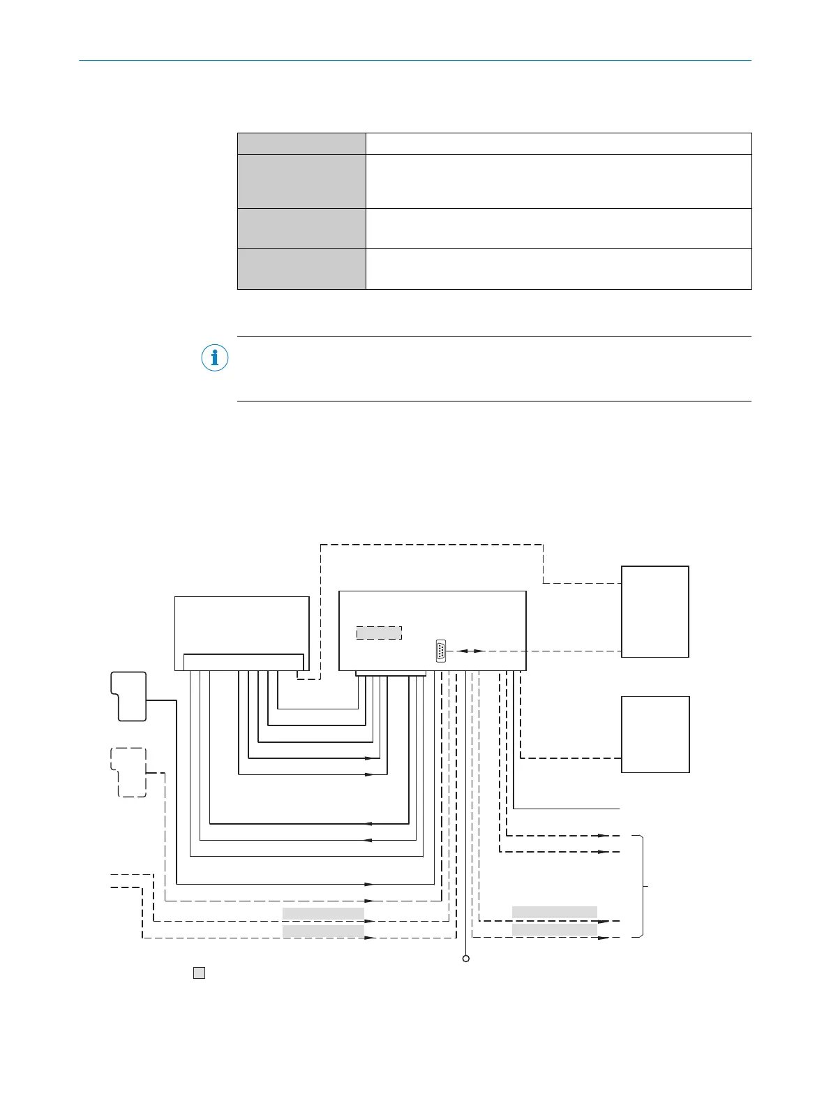
13.6 Connection diagrams of connection module CDB620-001
13.6.1 Connection of the device to CDB620-001
Device = Lector621 ECO = V2D621x-xxxxxYx (serial variant, Y = D or E)
„V
S
”
“Host 1”
“Aux 1”
“Result 2”
“Result 1”
“CAN”
“Sensor 2”
“Sensor 1”
“AUX”
CAN bus
“Result 1”
“Result 2”
PLC
“External output 2”
CDB620-001
Connection module 6
“Host 1”
“Aux 1”
RS-232
HOST/PLC
Further data
processing 8
PC
Configuration
Diagnostics
Image display
Interfaces 3
Device 2
“USB” (Aux 2) 4, Image transfer 5
RS-232/RS-422
USB
“Aux 2”
“Sensor 2”
“Sensor 1”
“External input 2”
“External input 1”
CMC600
1
ã
â
V
S
ß
= á
“External output 1”
à 9
7
Figure 61: Connection of the device (serial variant) to peripherals via CDB620-001 (overview)
1
External trigger sensor, e.g. for read cycle generation
ANNEX 13
8022502/15NT/2020-02-11 | SICK O P E R A T I N G I N S T R U C T I O N S | Lector621
103
Subject to change without notice