Load (e.g. PLC) 4
GND
For inductive load: 6
V
out
Device 1
Aux
(RS-232)
CDM420-0006
CMC600 3
+24 V* (V
S
)
CAux Out B
36
GND
6
Shield
“External
output A” 2
5
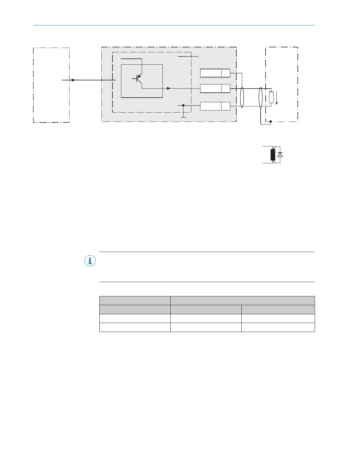
Figure 60: Wiring external digital outputs “Aux Out 1” and “Aux Out 2” of the device in the connection module CDM420-0006
1
Device
2
Logical “External output” in the device
3
The optional CMC600 parameter cloning module is required in the connection module in order to be able to use the
additional external digital inputs and outputs of the device
4
Load (e.g. PLC)
5
Output voltage V
out
6
With inductive load: see note
Inductive load
NOTE
Provide an arc-suppression switch at the digital output if inductive load is present.
b
Attach a freewheeling diode directly to the load for this purpose.
Table 53: Assignment of placeholders to the digital outputs
Device CDM420-0006
External output A Signal B Terminal C
1 Aux Out 1 40
2 Aux Out 2 30
Functional principle of the external digital outputs
The device outputs the output states of its logical outputs “External output 1” and
“External output 2” via its serial Aux interface. By means of a software-controlled opera‐
tion, the CMC600 automatically adopts the states via the connecting cable and sets
them on its physical digital outputs “Aux Out 1” and “Aux Out 2” in the connection mod‐
ule.
13 ANNEX
102
O P E R A T I N G I N S T R U C T I O N S | Lector621 8022502/15NT/2020-02-11 | SICK
Subject to change without notice