4
Digital switching outputs, e.g. for signal lamps
5
Digital switching inputs e.g. for encoders, photoelectric sensors (trigger sensor)
6
External illumination unit, e.g. ICL
7
USB interface (only for temporary use as a service interface)
8
Configuration
9
Image display
ß
Diagnostics
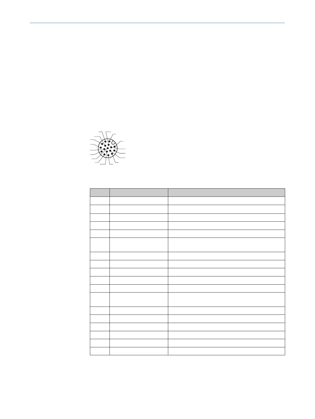
6.4 Pin assignments of electrical connections
6.4.1 Lector621
“Power/Serial data/CAN/I/O” connection
3
1
7
2
6
5
4
8
13
14
17
15
9
10
12
16
11
Figure 25: Male connector, M12, 17-pin, A-coded
Table 9: Pin assignment of the “Power/Serial data/CAN/I/O” connection
Pin Signal Function
1 GND Ground
2 V
S
Supply voltage
3 CAN L CAN bus (IN/OUT)
4 CAN H CAN bus (IN/OUT)
5 TD+ (RS-422/485), host Host interface (sender+)
6 TD– (RS-422/485), host
TxD (RS-232), host
Host interface (sender-)
7 TxD (RS-232), Aux Aux interface (sender)
8 RxD (RS-232), Aux Aux interface (receiver)
9 SensGND Digital input ground
10 Sensor 1 Digital input 1
11 RD+ (RS-422/485), host Host interface (receiver+)
12 RD– (RS-422/485), host
RxD (RS-232), host
Host interface (receiver–)
13 Result 1 Digital output 1
14 Result 2 Digital output 2
15 Sensor 2 Digital input 2
16 Result 3 Digital output 3
17 Result 4 Digital output 4
– – Shield
ELECTRICAL INSTALLATION 6
8022502/15NT/2020-02-11 | SICK O P E R A T I N G I N S T R U C T I O N S | Lector621
41
Subject to change without notice