6
Adapter cable (male connector, USB, Micro-B type / male connector, USB, type A)
7
Configuration with SOPAS ET, image display or reading diagnostics
6.3.3 Example applications
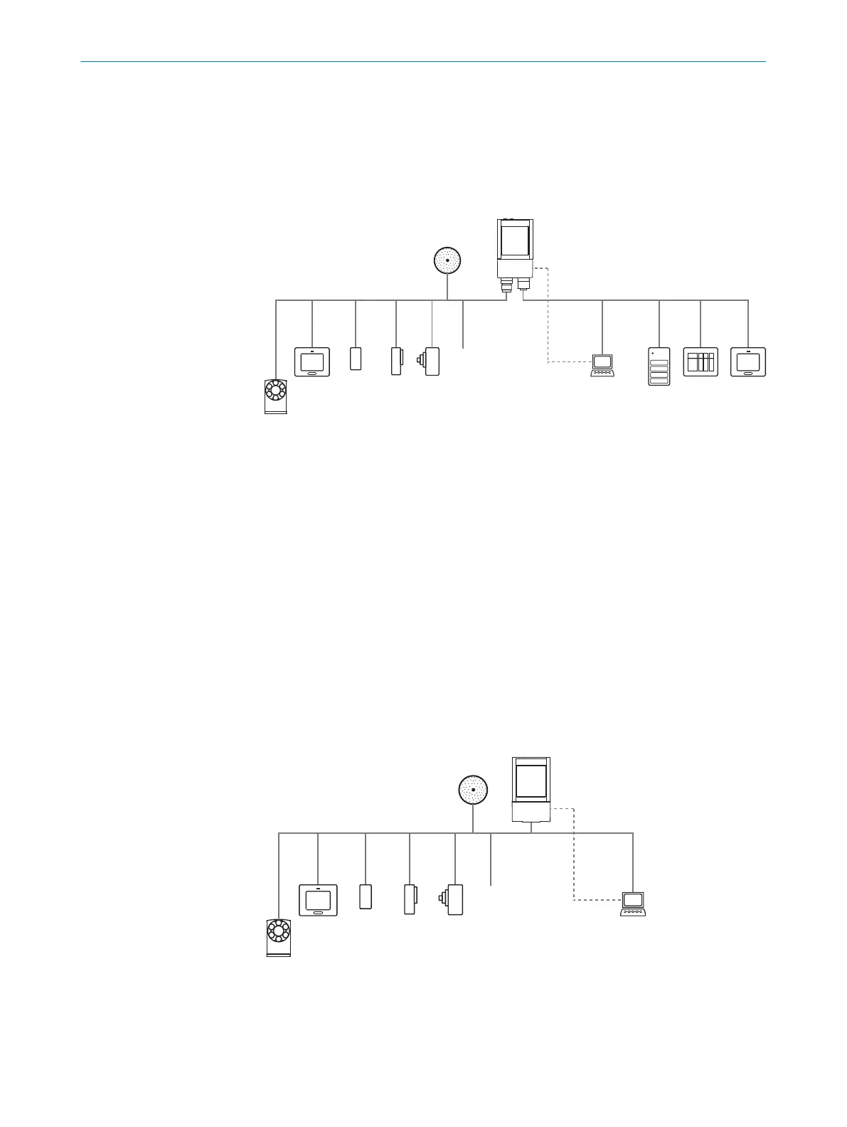
Lector621
Ethernet
USB 7
Lector621
V
S
PC
FTP à
SOPAS ETSOPAS ET
Configuration 8
Image display 9
Diagnostics ß
HMI á
PLC 3
PLC 3
Digital
switching
inputs 5
Digital
switching
outputs 4
serial 2
EthernetSerial Data, CAN, I/O
CSN (CAN sensor
network) 1
External illumination, e.g. ICL 6
Figure 23: Lector621: connection options
1
CSN (CAN sensor network)
2
Serial
3
PLC (programmable logic controller)
4
Digital outputs, e.g. for signal lamps
5
Digital inputs e.g. for encoders, photoelectric sensors (trigger sensor)
6
External illumination unit, e. g. ICL
7
USB interface (only for temporary use as a service interface)
8
Configuration
9
Image display
ß
Diagnostics
à
FTP server (image storage)
á
HMI interface
Lector621 ECO
RS-232
USB 7
Lector621 ECO
V
S
PC
SOPAS ETSOPAS ET
Configuration 8
Image display 9
Diagnostics ß
PLC 3
Digital
switching
inputs 5
Digital
switching
outputs 4
serial 2
Serial Data, CAN, I/O
CSN (CAN sensor
network) 1
External illumination, e.g. ICL 6
Figure 24: Lector621 ECO: connection options
1
CSN (CAN sensor network)
2
Serial
3
PLC (programmable logic controller)
6 ELECTRICAL INSTALLATION
40
O P E R A T I N G I N S T R U C T I O N S | Lector621 8022502/15NT/2020-02-11 | SICK
Subject to change without notice