In the case of open end cables, make sure that bare wire ends do not touch. Wires
must be appropriately insulated from each other.
Wire cross-sections of the data and switching signal cables have to also be designed in
accordance with the applicable national standards.
6.2.1 Data cables
NOTE
Layout of data cables
■
Use screened data cables with twisted-pair wires.
■
Implement the screening design correctly and completely.
■
To avoid interference, e.g. from switching power supplies, motors, clocked drives,
and contactors, always use cables and layouts that are suitable for EMC.
■
Do not lay cables over long distances in parallel with power supply cables and
motor cables in cable channels.
Serial data transmission (RS-232, RS422/485)
•
The possible length of cable between the device and host computer depends on
the following factors:
°
The physical version of the host interface selected
°
The data transmission rate set in the device
For further information, see "Wiring data interfaces", page 45.
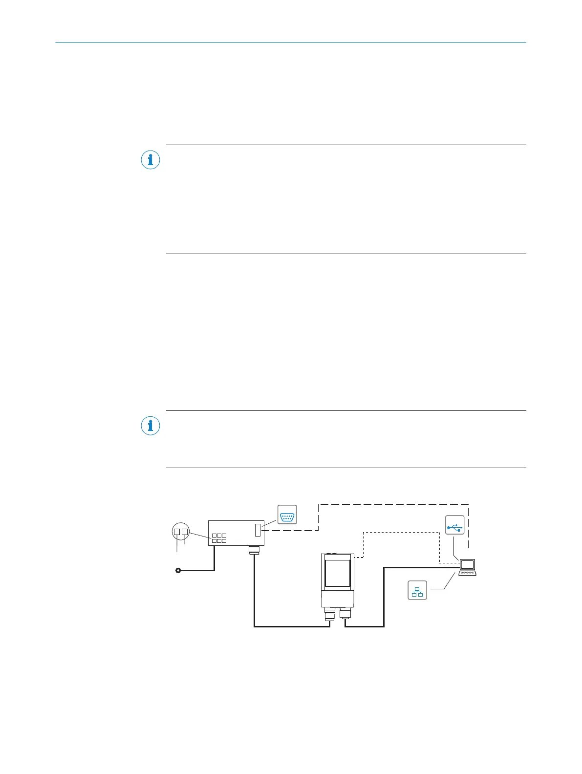
6.3 Connection diagrams
6.3.1 Service mode connection schematic
This operating mode is recommended for initial commissioning of the device.
NOTE
The USB interface of the device is used in industrial environments only as a service
interface for temporary use (e.g. for configuration, troubleshooting). Permanent use in
operational use of the system as a host interface is not intended.
Lector621
Lector621
Connection module 2
SerialSerial
Configuration
Image display
Diagnostics
SOPASSOPAS
"Power/Serial Data/
CAN/I/O"
(Aux 1, Host 1)
...
...
1
2
V
S
1
GND
PC
Cable 3
"Serial RS-232" (Aux 1) 4
"Ethernet" (Aux 2,
image transfer) 7
"USB" (Aux 3, for
temporary use only) 5
V
S
Cable 6
EthernetEthernet
USBUSB
Cable ß
9
Cable 8
Figure 19: Lector621 commissioning: connection block diagram
1
Supply voltage V
S,
(V
S
= U
V
)
2
Connection module CDB650-204 or CDM420-0006
3
Null modem cable (female connector, D-Sub, 9-pin/female connector, D-Sub, 9-pin),
crossed TxD and RxD
ELECTRICAL INSTALLATION 6
8022502/15NT/2020-02-11 | SICK O P E R A T I N G I N S T R U C T I O N S | Lector621
37
Subject to change without notice