Pin Signal Function Wire color
15 SensGND Digital input ground White-black
13.3.4 Host interface RS-232 via CDB/CDM connection module to host (PC)
Device Connection modules
Lector621 CDB650-204, CDM420-0006, -0007
Lector621 ECO CDB620-001, CDM420-0001, -0004, -0006, -0007
Adapter cable
Part no. 2020319 (3 m), unshielded
Ambient temperature range:
For mobile installation: –5 °C to +90 °C, for fixed installation: –30 °C to +90 °C
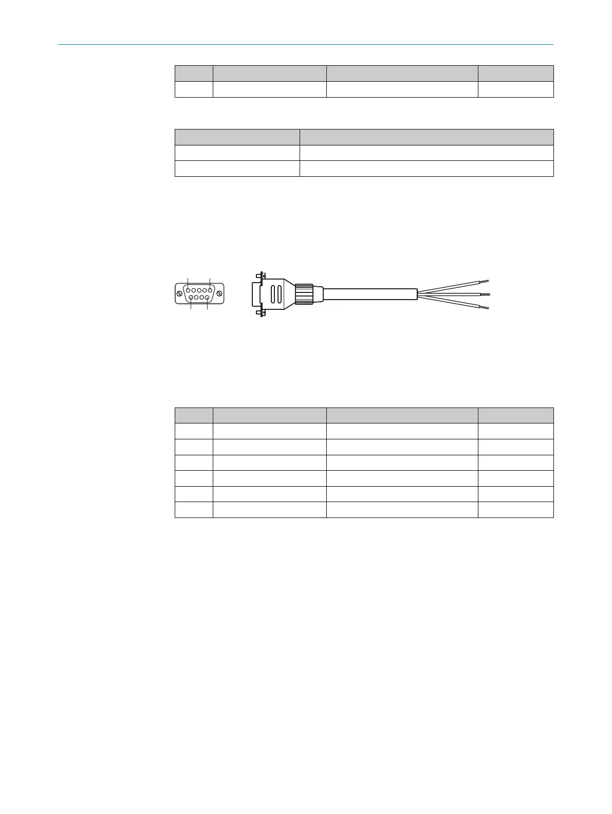
Figure 35: Adapter cable, part no. 2020319 (3 m)
1
Female connector, D-Sub, 9-pin (view from front)
2
Illustration may differ
Table 30: Signal assignment of adapter cable with open end
Pin Signal at PC Function Wire color
1 – – –
2 RxD (RS-232), host Host interface (receiver) Brown
1)
3 TxD (RS-232), host Host interface (sender) Blue
2)
4 – – –
5 GND Ground Black
6 ... 9 – – –
1)
Connect to the terminal “TxD Host” in the CDB/CDM connection module
2)
Connect to the terminal “RxD Host” in the CDB/CDM connection module
13.4 Connection diagrams of connection module CDB650-204
13.4.1 Connection of the device to CDB650-204
Device = Lector621 = V2D621x-xxxxxYx (Ethernet variant, Y = B or C)
ANNEX 13
8022502/15NT/2020-02-11 | SICK O P E R A T I N G I N S T R U C T I O N S | Lector621
75
Subject to change without notice