Pin Signal Function Wire color
12 RD– (RS-422/485), host
RxD (RS-232), host
Host interface (receiver–) Red-blue
13 Result 1 Digital output 1 White-green
14 Result 2 Digital output 2 Brown-green
15 Sensor 2 Digital input 2 White-yellow
16 Result 3 Digital input 3 Yellow-brown
17 Result 4 Digital input 4 White-gray
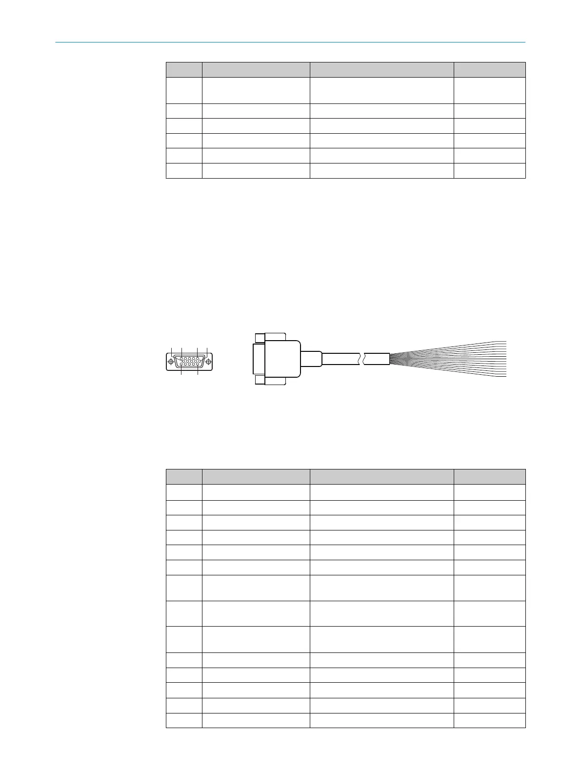
13.3.3 “Power/SerialData/CAN/I/O” connection to customer-specific connection equipment or control
cabinet
Adapter cable
For Lector621 ECO
Part no. 2043413 (2 m), shielded
Ambient temperature range: 0 °C to +80 °C
The shield braid of the cable has contact with the metal housing of the female connec‐
tor.
Figure 34: Adapter cable, part no. 2043413
1
Female connector, D-Sub-HD, 15-pin (view from front)
2
Illustration may differ
Table 29: Signal assignment of adapter cable with open end
Pin Signal Function Wire color
1 V
S
Supply voltage Red
2 RxD (RS-232), Aux AUX interface (receiver) Violet
3 TxD (RS-232), Aux AUX interface (sender) Yellow
4 Sensor 2 Digital input 2 Red-black
5 GND Ground Black
6 RD+ (RS-422) Host Host interface (receiver+) Light blue
7 RD– (RS-422), Host
RxD (RS-232), host
Host interface (receiver–) Blue
8 TD+ (RS-422), Host Host interface (sender+) Light-gray or
turquoise
9 TD– (RS-422), Host
TxD (RS-232), host
Host interface (sender-) Green
10 CAN H CAN bus (IN/OUT) Gray
11 CAN L CAN bus (IN/OUT) Pink
12 Result 1 Digital output 1 Brown
13 Result 2 Digital output 2 Orange
14 Sensor 1 Digital input 1 White
13 ANNEX
74
O P E R A T I N G I N S T R U C T I O N S | Lector621 8022502/15NT/2020-02-11 | SICK
Subject to change without notice