4
V2D621x-xxxxxYx (Ethernet variant, Y = B or C): adapter cable (female connector, M12, 17-pin, A-coded / male connec‐
tor, D-Sub-HD, 15-pin)
5
Load (e.g. PLC)
6
Output voltage V
out
7
With inductive load: see note
8
Connection module: female connector, D-Sub-HD, 15-pin
9
V2D621x-xxxxxYx (Ethernet variant, Y = B or C): male connector, M12, 17-pin, A-coded
Inductive load
NOTE
Provide an arc-suppression switch at the digital output if inductive load is present.
b
Attach a freewheeling diode directly to the load for this purpose.
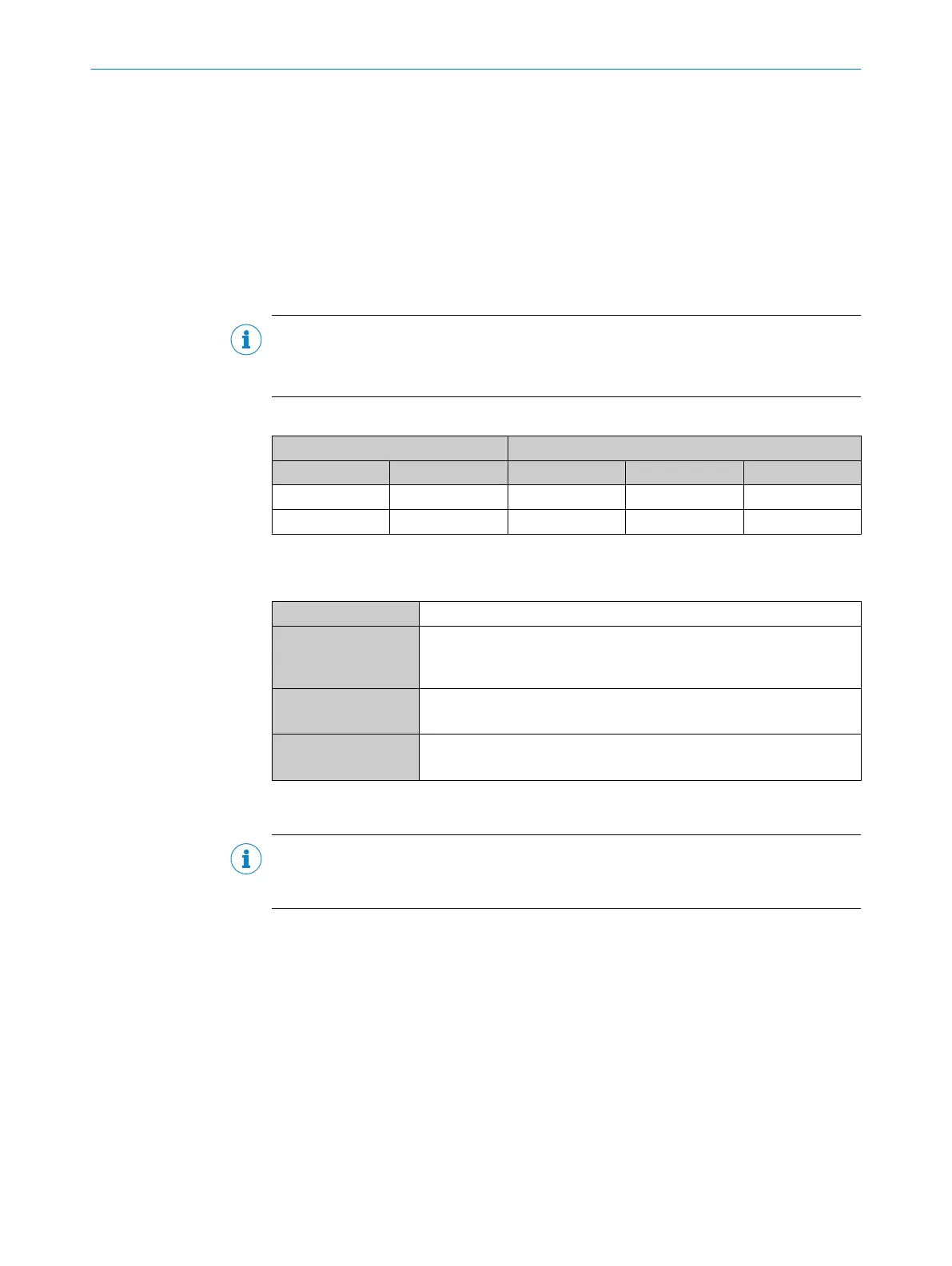
Table 51: Assignment of placeholders to the digital outputs
Device CDM420-0006
Output A Pin B Pin C Signal D Terminal E
Result 1 13 12 Result 1 14
Result 2 14 13 Result 2 15
Characteristic data of the digital outputs
Table 52: Characteristic data of the digital outputs “Result 1” and “Result 2”
Type Switching
Switching behavior PNP switching to supply voltage V
S
Default settings in the device: no function, logic: not inverted (active
high)
Properties
•
Short-circuit protected + temperature protected
•
Not electrically isolated from the supply voltage V
S
Electrical values 0 V ≤ V
out
1)
≤ V
S
(V
S
−1.5 V) ≤ V
out
≤ V
S
at I
out
2)
≤ 100 mA
1)
Output voltage.
2)
Output current.
NOTE
Assign the functions for the digital outputs in the device using a configuration tool, e.g.
the configuration software SOPAS ET.
13.5.10 Wiring digital outputs “External output 1” and “External output 2” of the device in the
CDM420-0006
Device = Lector62x = ICR620x-xxxYxx (serial variant, Y = 0, 1 or 2), ICR620x-xxx5xx (Ethernet variant)
ANNEX 13
8022502/15NT/2020-02-11 | SICK O P E R A T I N G I N S T R U C T I O N S | Lector621
101
Subject to change without notice