°
Screw the screws no more than 5 mm into the threaded mounting holes or
sliding nuts.
°
To do so, either use all 4 threaded mounting holes on the rear of the device
or the two sliding nuts on the side of the device.
°
Attach the separately-ordered, optional SICK mounting system using the slid‐
ing nuts on the device. Mounting systems are available as accessories, see
"Accessories", page 69.
2. Align the device taking into consideration the field of view (see "Field of view
diagrams", page 31) and the application circumstances (see "Installation require‐
ments", page 24).
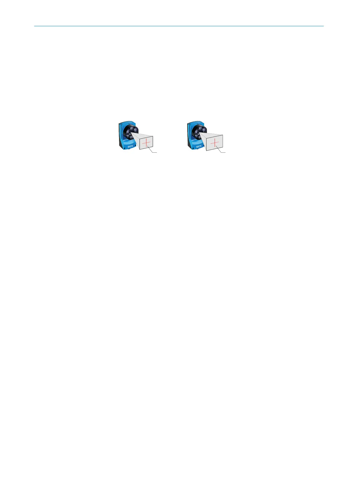
FOV 3
1.3 Mpx image sensor 1 1.9 Mpx image sensor 2
FOV 3
Figure 7: Resolution-dependent field of view geometries
1
Device with image sensor 1.3 Mpx
2
Device with image sensor 1.9 Mpx
3
Field of view
3. Connect the device to interfaces and supply voltage when disconnected from
voltage, see "Connecting the device", page 42.
✓
The Ready status LED lights up green.
4. Perform fine adjustment.
5
MOUNTING
36
O P E R A T I N G I N S T R U C T I O N S | Lector63x Flex C-mount and S-mount 8018071/1E1C/2021-12-16 | SICK
Subject to change without notice