6.3 Connection diagrams
6.3.1 Connection principle
SOPASSOPAS
Configuration 3
Image display 4
Diagnostics 5
Power ...
Ethernet
USB 2
Cable 6 Cable 7
Connection
module 1
...
...
1
2
V
S
GND
USBUSB
EthernetEthernet
Lector
®
63x
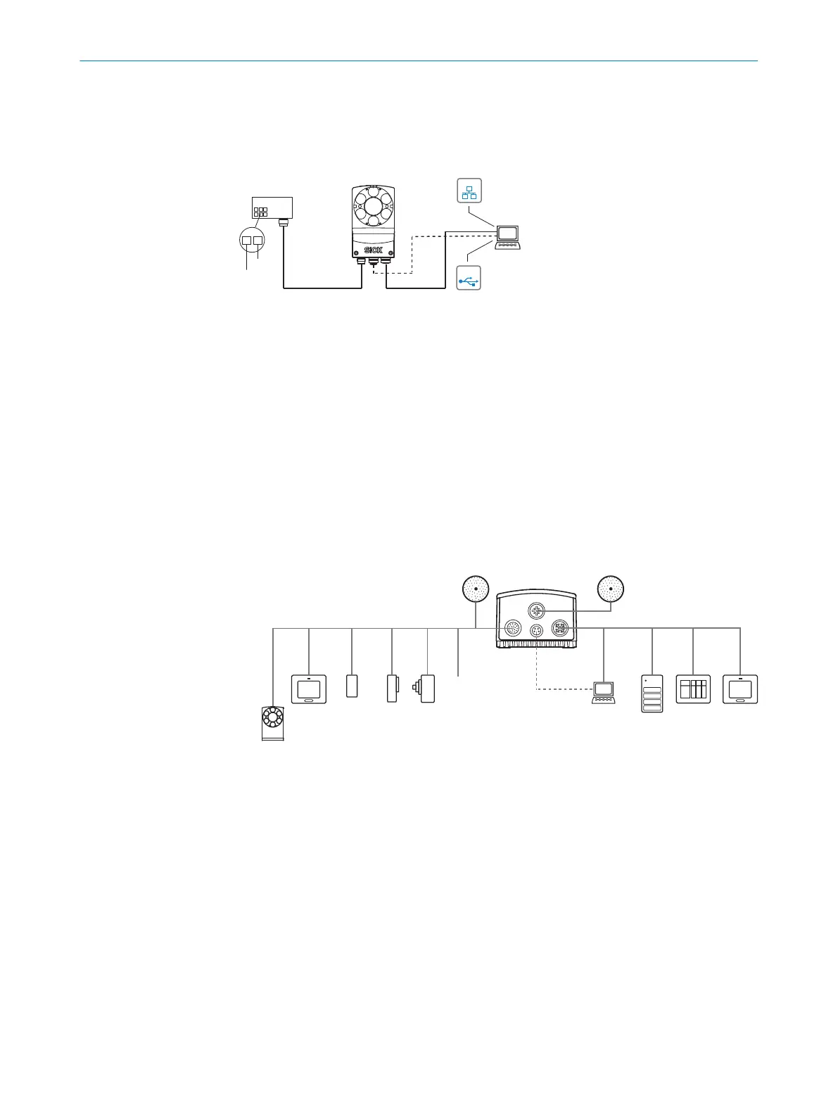
Figure 11: Connection block diagram
1
Connection module CDB650-204 or CDM420-0006
2
Alternative USB, adapter cable (male connector, M8, 4-pin/male connector, USB, type A)
3
Configuration
4
Image display
5
Diagnostics
6
CDB650-204: Cable 1:1 (male connector, M12, 17-pin, A-coded/female connector, M12,
17-pin, A-coded)
CDM420-0006: Adapter cable (female connector, M12, 17-pin, A-coded/male connector,
D-Sub-HD, 15-pin)
7
Adapter cable (male connector, M12, 8-pin, X-coded/male connector, RJ45, 8-pin)
6.3.2 Example applications
Ethernet
USB
Lector
®
63x
Power I/O
External light
Ethernet
USB
External illumination ICL 1
V
S
External illumination
ICL, VLR, CCS 2
PC
FTP
SOPASSOPAS
Configuration 8
Image display 9
Diagnostics ß
HMI
PLC
PLC 5
Digital
switching
inputs 7
Digital
switching
outputs 6
serial 4
Ethernet
CSN (CAN sensor
network) 3
Figure 12: Facilities for connecting
1
External ICL illumination
2
External ICL, VRL, CCS illumination
3
CSN (CAN sensor network)
4
Serial
5
PLC (programmable logic controller)
6
Digital outputs, e.g. for signal lamps
7
Digital inputs e.g. for encoders, photoelectric sensors
8
Configuration
9
Image display
ß
Diagnostics
ELECTRICAL INSTALLATION 6
8018071/1E1C/2021-12-16 | SICK O P E R A T I N G I N S T R U C T I O N S | Lector63x Flex C-mount and S-mount
41
Subject to change without notice