Device 1 CDM420-0006 Host
5
.
.
.
TD+
TD‒
RD+
RD‒
RD+
RD‒
TD+
TD‒
GND
GND
GND
11
12
1
5
8
9
6
7
6
24
T+
34
T‒/TxD
25
R+
35
R‒/RxD
36
GND
6
Shield
RS-422 RS-422
ON
OFF
S2 : RS 485
ON
OFF
S3: Term 422
S2
OFF
S3
OFF
120 Ω
2
3
1
7
2
6
5
4
8
13
14
17
15
9
10
12
16
11
110
15
6
11
5
4 3
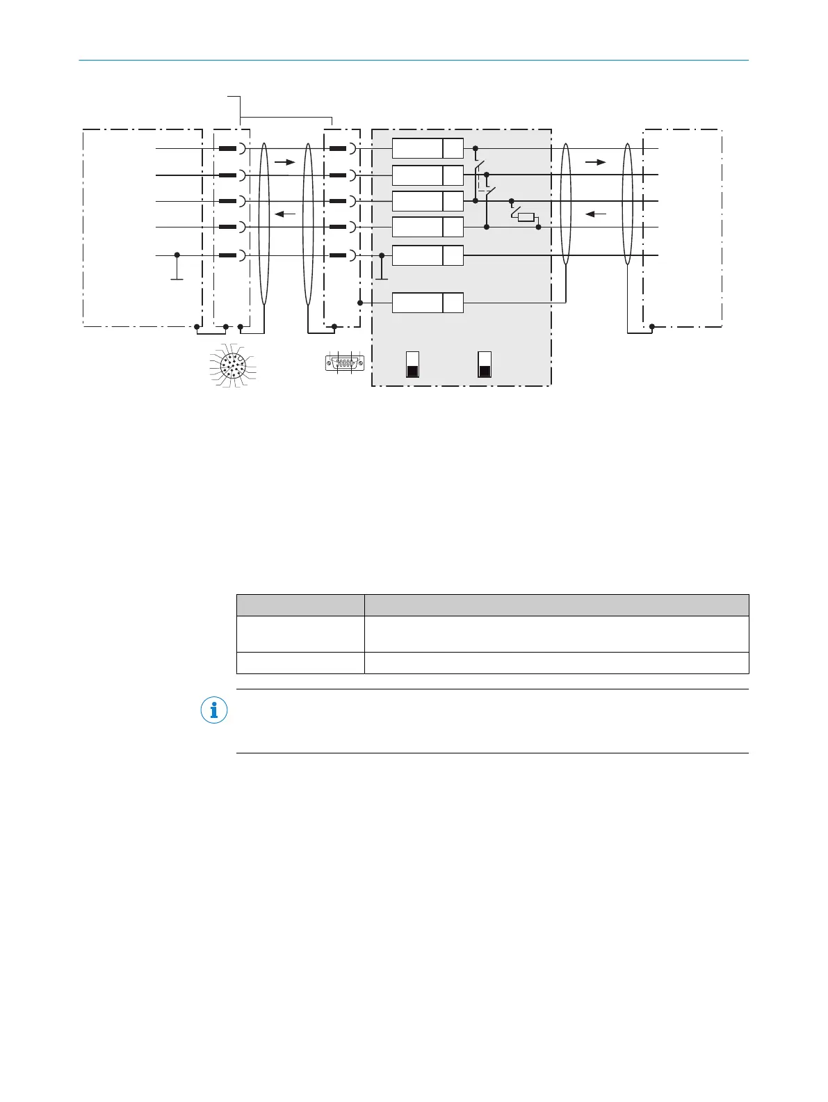
Figure 34: Wiring data interface RS-422 of the device in connection module CDM420-0006.
1
Device
2
Adapter cable (male connector, D-Sub-HD, 15-pin / female connector, M12, 17-pin, A-coded)
3
Connection module: female connector, D-Sub-HD, 15-pin
4
Device: male connector, M12, 17-pin, A-coded
Function of switch S3
Table 31: Switch S3: Term 422
Switch setting Function
ON Terminates the RS-422 receiver in the device to improve the noise ratio
on the line
OFF No termination
NOTE
Activate the RS-422 data interface (“Point-to-Point” option) in the device with a configu‐
ration tool, e.g. the configuration software SOPAS ET.
The requirements and restrictions apply when using the RS-422 data interface:
•
The relevant interface drivers for the device comply with the standard in accord‐
ance with RS-422.
•
The connection shown above is configured for operation of the host with perma‐
nently activated drivers (often described as “RS-422 operation”).
13.3.6 Wiring the CAN interface of the device in the CDM420-0006
Device = Lector63x = V2D63xx-xxxxBx
Not considered: connection and looping through of the supply voltage, connection of a trigger sensor for read cycle
generation (e.g. at the master)
ANNEX 13
8018071/1E1C/2021-12-16 | SICK O P E R A T I N G I N S T R U C T I O N S | Lector63x Flex C-mount and S-mount
87
Subject to change without notice