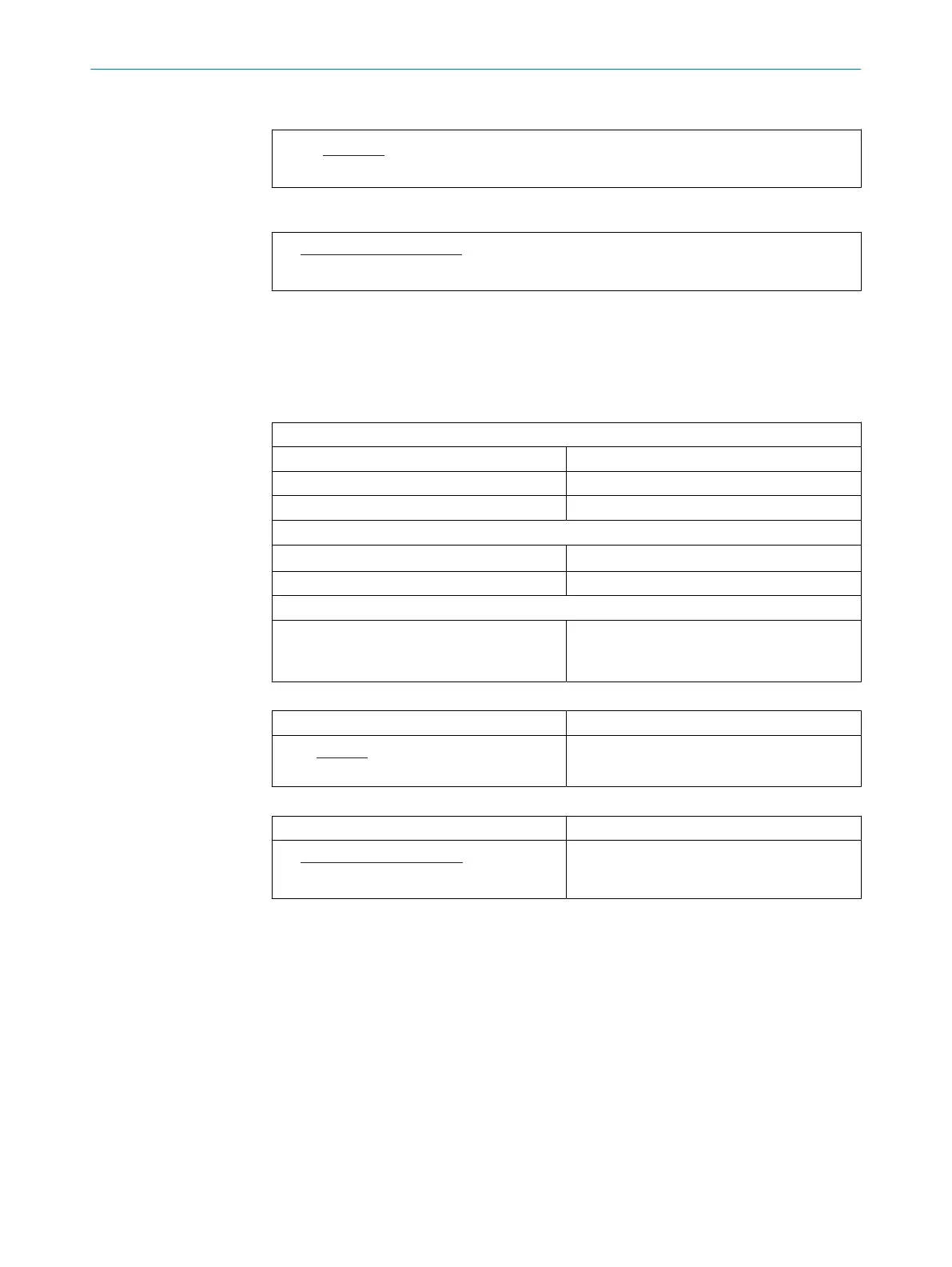
Formula for the voltage drop to be considered
I•2•L
•ρ•(1 + α•(T - T
0
))
Δ V =
A
Formula for permissible length of cable
L =
2•I•ρ•(1 + α•(T - T
0
))
Δ V•A
Sample calculations
Prerequisites:
•
Steady state of the voltage supply
•
Only applies for copper cable material
Table 6: Values used in both example calculations
Cable properties
A = 0.34 • 10
-6
m² Cross-section of the cable surface [m
2
]
ρ = 1.72 • 10
-8
Ωm Specific resistance of copper [Ωm]
α = 3.9 • 10
-3
K
-1
Temperature coefficient of copper [1/K]
Ambient conditions
T
0
= 20°C Reference temperature [°C]
T = 80°C Cable temperature [°C]
Cable load
I = P/U = 1.46A
P = 35W
U= 24V
Load current I [A]
Supply voltage U [V]
Maximum expected power consumption P
Table 7: Example: voltage drop to be considered for cable part no. 2096241
L = 10m Cable length [m]
I•2•L
•ρ•(1 + α•(T - T
0
))
Δ V =
= 1.82 V
A
Voltage drop ΔV [V]
Table 8: Calculation of the cable length for allowed voltage drop of 1.82V
ΔV = 1.82V Voltage drop on the cable [V]
L =
2•I•ρ•(1 + α•(T - T
0
))
Δ V•A
= 10 m
Permissible length of cable [m]
6.4 Cable reserve on system plug
Allow for sufficient cable reserve of the supplied cables at the system plug. You can
easily exchange the device with the cable reserve if needed.
Keep the cable reserve only long enough that the system plug cannot be accidentally
plugged into an adjacent device when replacing the device! This prevents a device with
an incorrect configuration being put into operation. Experience has shown that 200 to
300mm of cable reserve on the device is ideal.
The reserve cable should be laid as a drip loop so no moisture (e.g., condensation) is
directed towards the device but instead drips off the cable beforehand.
ELECTRICAL INSTALLATION 6
8027119/0000/2022-11 | SICK O P E R A T I N G I N S T R U C T I O N S | multiScan136
43
Subject to change without notice