6.5 Connection diagram
NOTE
The recommended connecting cables and their associated technical data can be found
on the online product page.
The call is made via the SICK Product ID: pid.sick.com/{P/N}/{S/N}
{P/N} corresponds to the part number of the product, see type label.
{S/N} corresponds to the serial number of the product, see type label (if indicated).
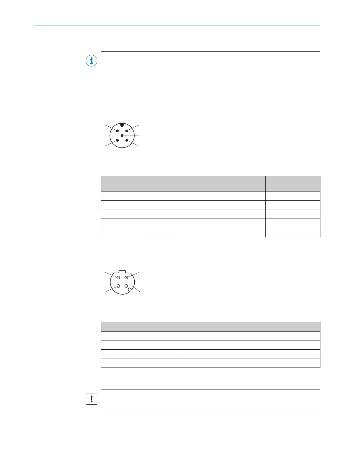
PWR connection
Figure 36: Male connector, M12, 5-pin, A-coded
Table 9: Pin assignment for PWR connection
Contact Signs Description Wire color, part num‐
ber 2095733
1)
1 Vs Supply voltage: +9 ... +30VDC Brown
2 IN2/OUT2 Digital input 2 / digital output 2 White
3 GND Supply voltage: 0V Blue
4 IN1/OUT1 Digital input 1 / digital output 1 Black
5 IN3/OUT3 Digital input 3 / digital output 3 Gray
1)
Data only valid when using the specified connecting cable with flying leads, which is available as an
accessory
Ethernet connection
Figure 37: M12 female connector, 4-pin, D-coded
Table 10: Pin assignment for Ethernet connection
Contact Signs Description
1 TX+ Sender+
2 RX+ Receiver+
3 TX- Sender-
4 RX- Receiver-
6.6 Connecting the device electrically
NOTICE
Observe the wiring instructions, see "Wiring instructions", page 39.
6 ELECTRICAL INSTALLATION
44
O P E R A T I N G I N S T R U C T I O N S | multiScan136 8027119/0000/2022-11 | SICK
Subject to change without notice