EasyManua.ls Logo

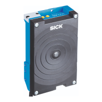
SICK RFH630

SICK RFH630
40 pages
To Next Page IconTo Next Page
To Previous Page IconTo Previous Page
Loading...
Chapter 3 Technical Information
RFID write/read device RFH630 (HF)
20 © SICK AG · Germany · All rights reserved · Subject to change without notice 8014957/YSU6/2016-01-08
Electrical installation
3.6 Installation steps
3.6.1 Block diagram: wiring the CDB620-001 connection module
RFH630-1102101
“DC 10 V ... 30 V”
“Sensor 2”
“Host 1” (serial)
“Host 1” (serial)
Aux 1” (serial)
“CAN”
“Result 2”
“Result 1”
“Sensor 2”
“Sensor 1”
“Sensor 1”
DC 10 V ... 30 V
Write/read device
Antenna
Interface
“Ethernet” (Host 2/Aux 2)
RS-232/422
„AUX“
PC
HOST/PLC
Configuration
Diagnosis
SPS
CAN bus
SPS
“CAN”
“Result 1”
“Result 2”
Connection module
CDB620-001
RFH630
Photo-electric
switch
Reading clock
Photo-electric
switch
End of
reading pulse
(alternatively)
Incremental encoder
Path increment
Ethernet
“Host 2”
Ethernet
“Aux 2
Aux 1” (serial)
RS-232
CMC600
Transponder

Table of Contents

Other manuals for SICK RFH630

Related product manuals