2
Received light level is corrected
3
Low switching threshold H
4
Low switching threshold L
5
Switching threshold of the controller output
6 Change of the switching threshold when it falls between switching thresholds 3 and 4 over the duration of the update
cycle.
7
Received light level falls due to contamination
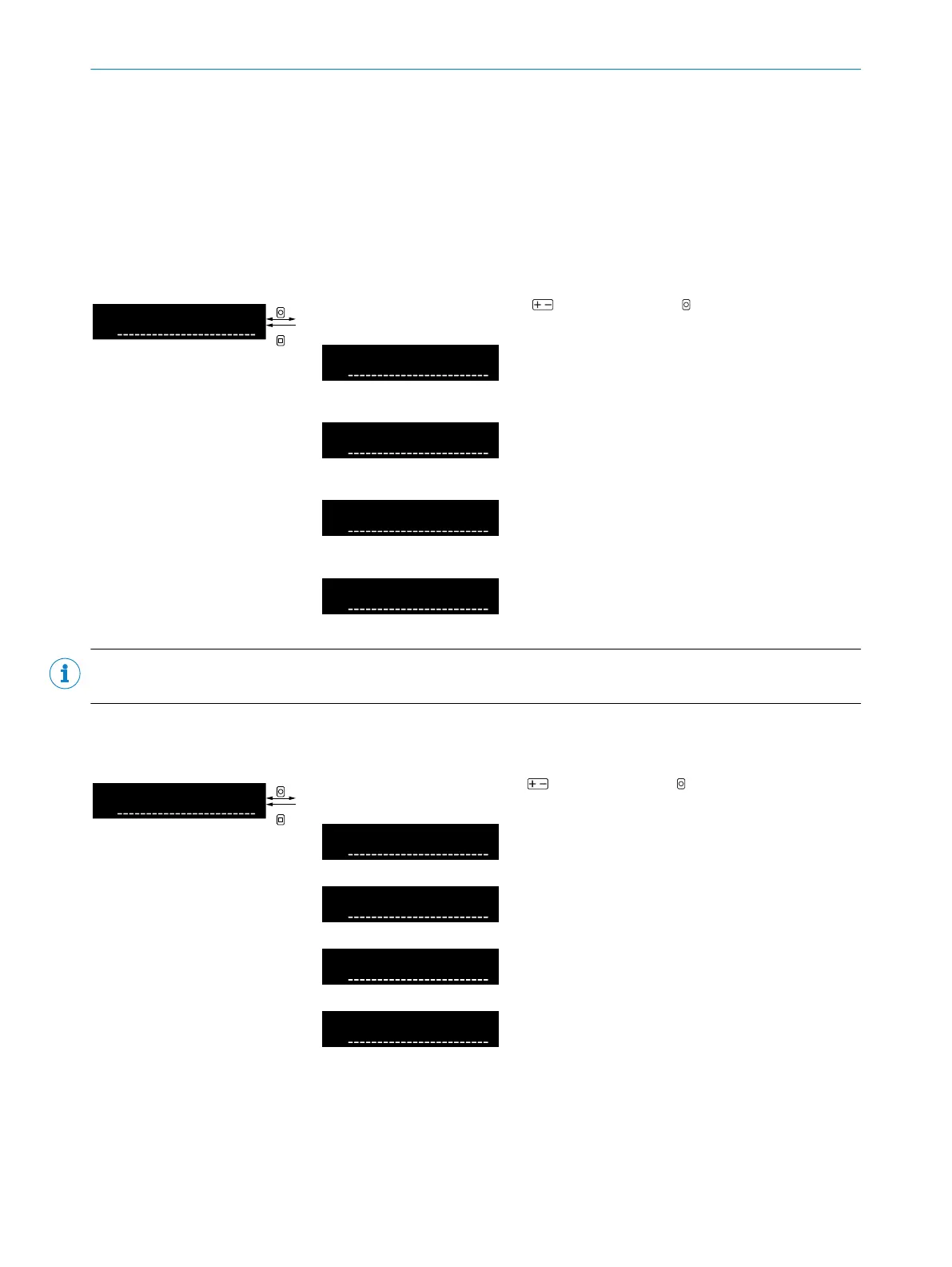
Table 31: Switching point adjustment (AutoAdapt)
Select AutoAdapt function using and confirm using OK. After confirmation,
the display returns to the higher-level menu.
Off
No switching point adjustment acti‐
vated
On with standard response time
(Update cycle of switching thresh‐
old: 3,000ms)
On with fast response time
(Update cycle of the switching
threshold: 1,000ms)
On with high speed response time
(Update cycle of the switching
threshold: 250ms)
NOTE
The AutoAdapt function can only be set for both channels together.
8.7.6 Sender power
Table 32: Sender power
Select set sender power using and confirm using OK. After confirmation,
the display returns to the higher-level menu.
Maximum sender power (current
received light value)
Median sender power (current
received light value)
Minimum sender power (current
received light value)
Sender power is regulated, if pos‐
sible, so that the received light
value is 5,000 digits (optimal work‐
ing range for many applications and
to avoid saturation of the received
light).
8 OPERATION
36
O P E R A T I N G I N S T R U C T I O N S | WLL80 Analog 8027947 /2022-12-14 | SICK
Subject to change without notice