Explanation of connection terminology used in Tables 1-3:
BN = Brown
WH = White
BU = Blue
BK = Black
n. c. = no connection
Q1 = switching output 1
Q2 = switching output 2
L+ = supply voltage (Uv)
M = common
L.ON = light operate
D.ON = dark operate
NOTE
The sensor outputs may come equipped with a factory set ON delay and/or OFF delay.
This is indicated by a Txx suffix at the end of the Model Number (Zxx18-xxxxxxTxx).
Connection and Output detail:
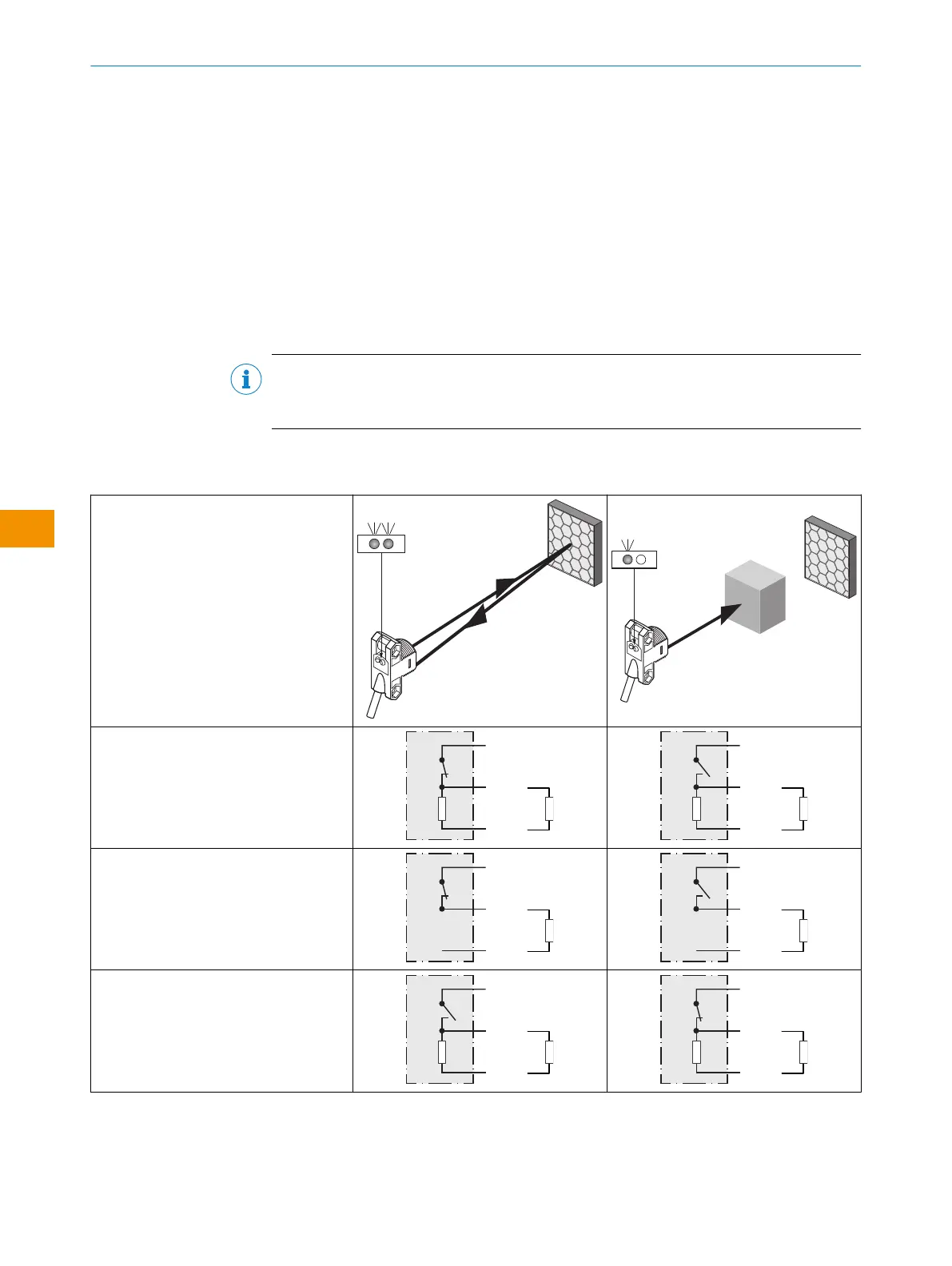
Table 1: Output Operation
ZLD18 / ZLE18
-x_xxxx = Q1 output
-xx_xxx = Q2 output
-xPxxxx
-x8xxxx
-xxPxxx
L.ON, PNP: Q (≤ 100 mA)
-xHxxxx
-x4xxxx
-xxHxxx
L.ON, PNP Open Collector Q (≤ 100 mA)
-xFxxxx
-x2xxxx
-xxFxxx
D.ON, PNP: Q (≤ 100 mA)
OPERATING INSTRUCTION
22
O P E R A T I N G I N S T R U C TI O N | ZLD18 / ZLE18 8021946.1HW1 /2022-11-14 | SICK
Subject to change without notice
en