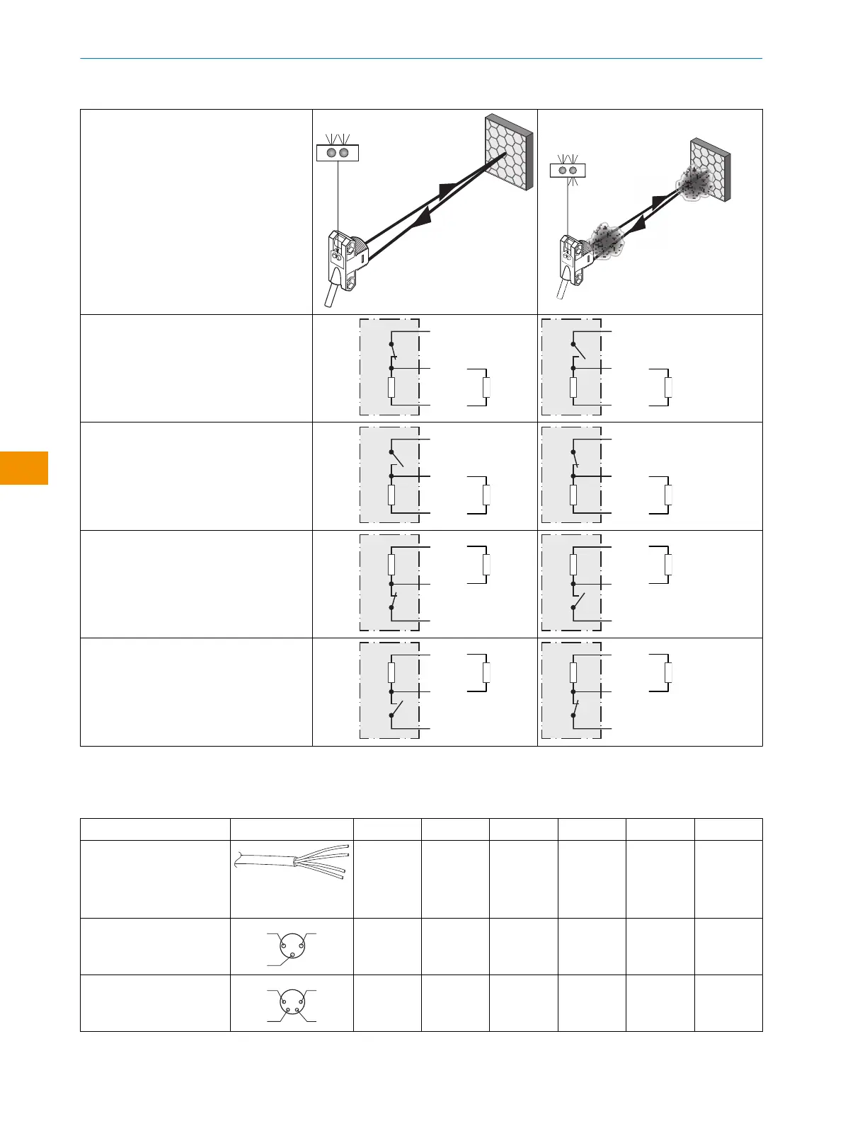
Table 2: Alarm/Health Operation
ZLD18 / ZLE18
-xx_xxx = Q2 output
Health/Alarm is always the Q2 output
-xxRxxx
Health, PNP (≤ 100 mA)
-xxTxxx
Alarm, PNP (≤ 100 mA)
-xxQxxx
Health, NPN (≤ 100 mA)
-xxSxxx
Alarm, NPN (≤ 100 mA)
Table 3: Connection Pinout
Zxx18 Diagram Pin 1 Pin 2 Pin 3 Pin 4 Pin 5 Pin 6
-xxx1xx
0.14 mm
2
AWG26
+ (L+)
BN
Q2
WH
- (M)
BU
Q1
BK
- -
-xxx2xx
M8, 3p
+ (L+)
(BN)
- - (M)
(BU)
Q1
(BK)
- -
-xxx3xx / -xxx5xx
M8, 4p
+ (L+)
(BN)
Q2
(WH)
- (M)
(BU)
Q1
(BK)
- -
OPERATING INSTRUCTION
24
O P E R A T I N G I N S T R U C TI O N | ZLD18 / ZLE18 8021946.1HW1 /2022-11-14 | SICK
Subject to change without notice
en