Operator control and monitoring
7.2 Displays and location of the connections
SIRIUS 3RM1 motor starter
Manual, 11/2013, A5E0345285095020A/RS-AB/002
107
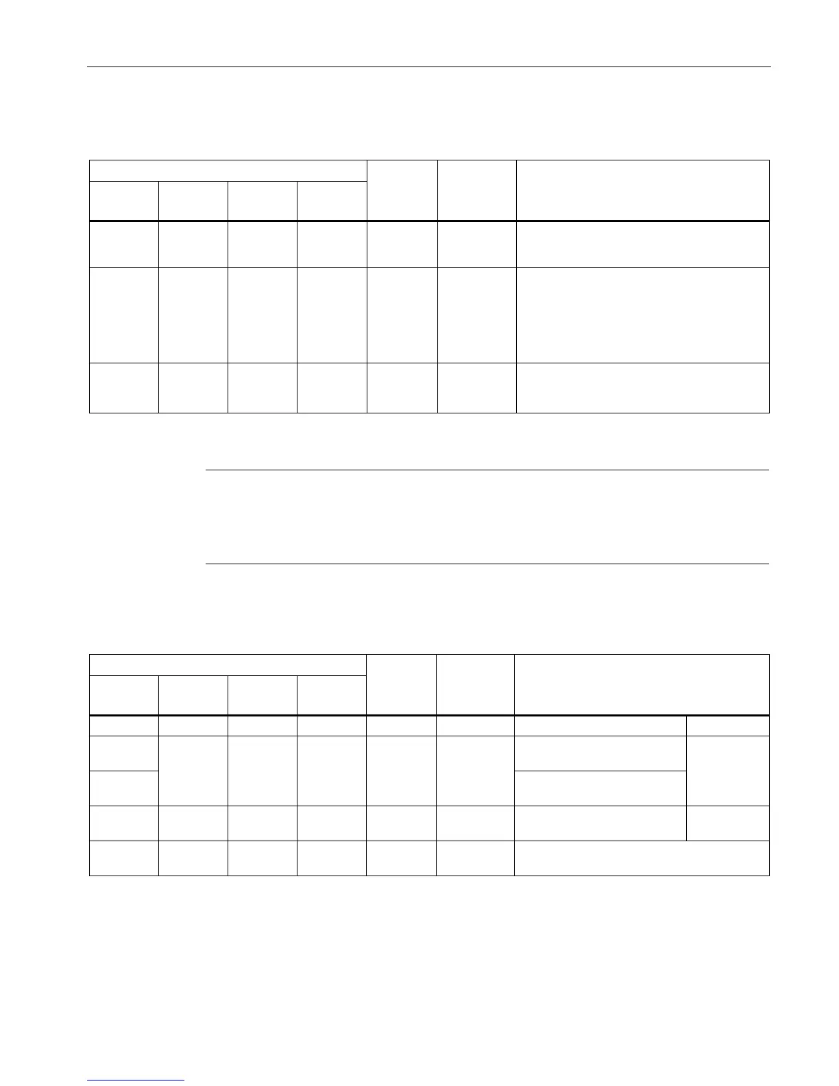
Reaction of
feedback
circuit
Possible cause/corrective measure
Yellow Red Off Green/off* Active -
• Overload trip motor protection
• Motor blocks during starting or operation
Flashing
yellow
Red Off Green/off* Active -
• No current flow despite ON command:
Check whether the connected load
fulfills the minimum current (Page 57).
• Phase failure: Check whether all three
phases are applied.
Flashing
red
Red Off Green/off* Active Active Malfunction: For information about
correcting faults, please refer to the section
"Fault rectification (Page 108)".
* = depending on the selected RESET MODE
Note
Difference between Standard and Failsafe
3RM11 Failsafe and 3RM13 Failsafe motor starters signal a phase failure immediately.
3RM10 and 3RM12 Standard motor starters signal a phase failure after 5 s.
Reaction of
feedback
circuit
Device status / operating mode
Yellow Red Green Green Self-test: Indicator test 2 s
Flickering
red
Current flow test: Current not
flowing
3 s
Flashing
red
Current flow test: Current
flowing
Flashing
yellow
Red Off Off Active Self-test: Overload tripping >5 s
Flashing
red
Red Off Off Active Active Overload trip failed