Configuration
4.2 Ambient conditions
SIRIUS 3RM1 motor starter
Manual, 11/2013, A5E0345285095020A/RS-AB/002
57
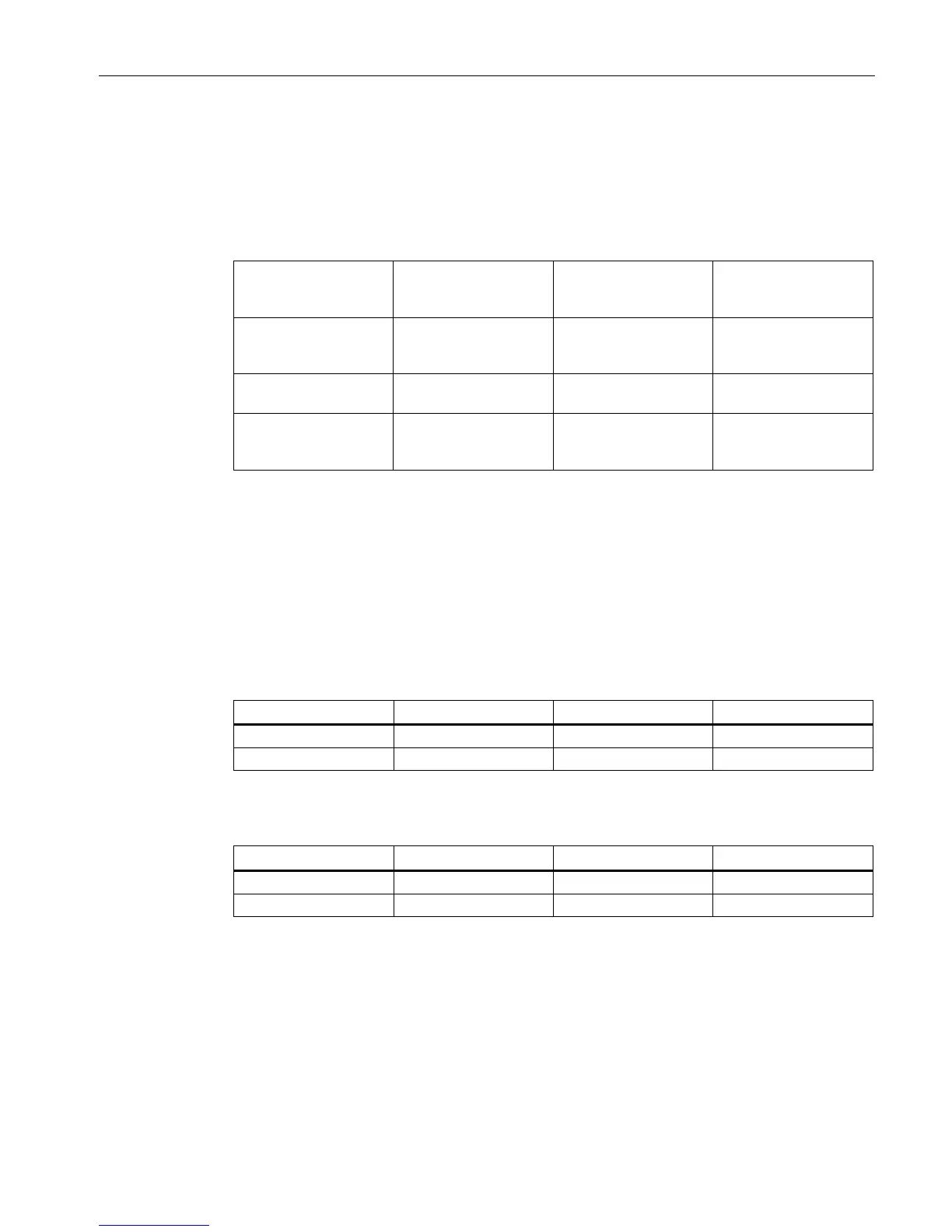
Permissible operating voltage
To be able to ensure safe isolation of the circuits from each other in accordance with IEC
60947-1, the following operating voltages are permissible:
Table 4- 1 Safe isolation of the 3RM1 motor starters
... to ...
Control circuit
(A1/A2, OUT, IN1-3,
M1/M2)
Signaling contacts
(98/95/96)
Main circuit
(1L1/3L2/5L3
2T1/4T2/6T3)
Control circuit
(A1/A2, OUT, IN1-3,
M1/M2)
Signaling contacts
(98/95/96)
Main circuit
(1L1/3L2/5L3
2T1/4T2/6T3)
The minimum load current is 20% of the set motor current, but at least the absolute minimum
current specified in the tables below.
The minimum load current differs in the case of Standard 3RM10/3RM12 and Failsafe
3RM11/3RM13 motor starters:
Table 4- 2 Minimum load current in the case of Standard 3RM10/3RM12 motor starters
Motorized load 0.05 A 0.14 A 0.6 A
Resistive load 0.05 A 0.14 A 0.6 A
Table 4- 3 Minimum load current in the case of Failsafe 3RM11/3RM13 motor starters
Motorized load 0.05 A 0.14 A 0.6 A
Resistive load 0.25 A 1 A 3.5 A
As soon as the minimum current limit is violated, fault detection (phase failure) picks up.