DRAFT 22.04.2008
Siemens SP00-000.814.09.01.02 ARCADIS
11.07 CS PS SP
Installing the WLAN Expansion 13
Page 13 of 78
Medical Solutions
2- 2Installi ng the WLAN Ex pansion
Installation with the Monitor Carriage, 07552024 0
NOTE
Perform this section only if the monitor carriage, 07552024,
is configured.
NOTE
As a prerequisite for installation, the 2-part network connec-
tion, 08079845, must already be installed.
If this is not the case, install the 2-part network connection
according to these installation instructions prior to install-
ing the WLAN Expansion.
Overview of Required Parts 0
Removing the Cover Panels 0
• Remove the large, rear cover panel on the monitor carriage.
• Remove the large, right side cover panel on the monitor carriage.
• Remove the top, rear cover panel (connection terminal) on the monitor carriage.
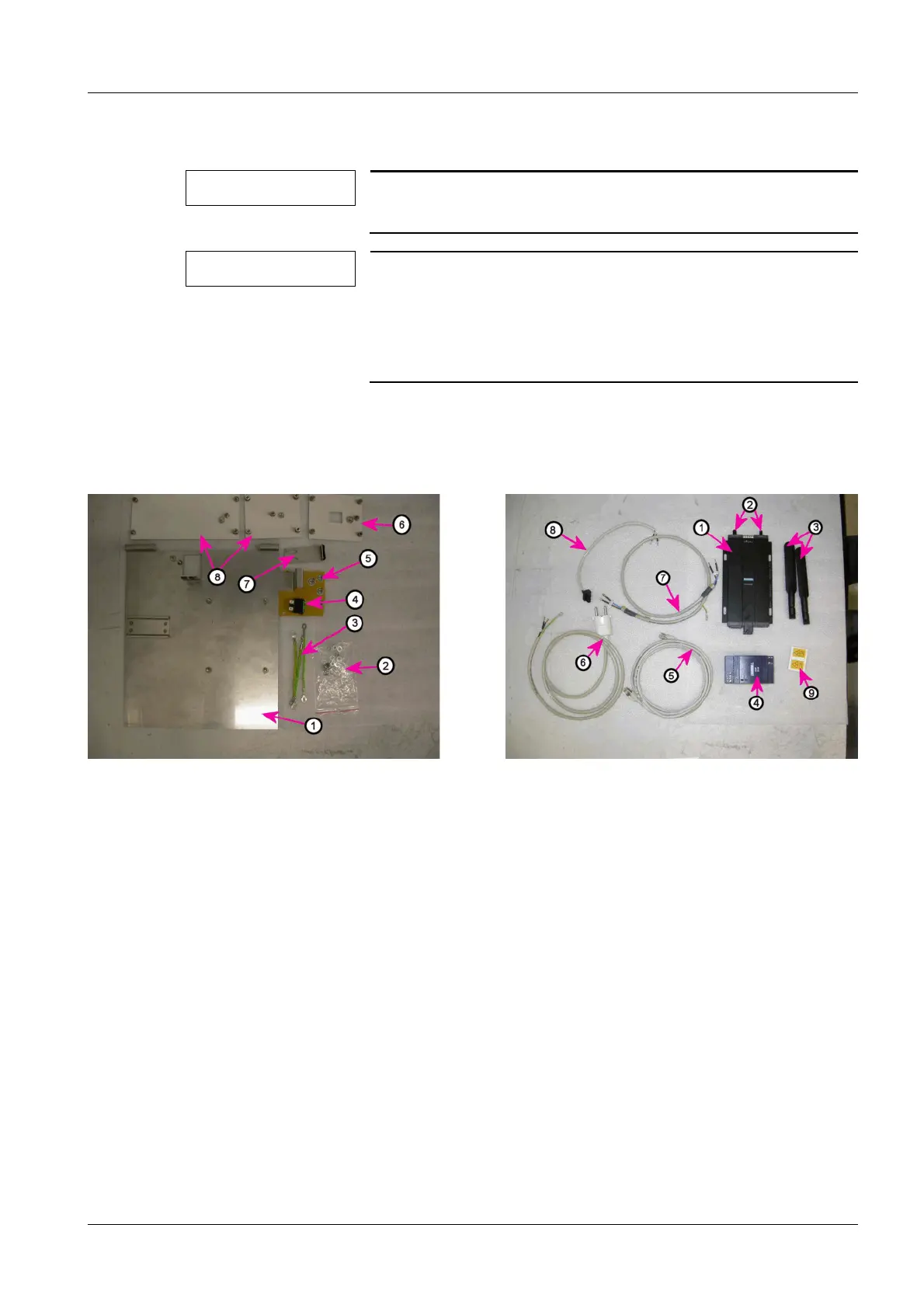
Fig. 2: WLAN Installation Parts
Pos. 1 Mounting plate
Pos. 2 Small parts (screws / nuts / plate washers)
Pos. 3 Ground wire
Pos. 4 WLAN power switch
Pos. 5 Ground wire symbol label
Pos. 6 Cover panel for WLAN power switch
Pos. 7 Mounting plate
Pos. 8 Blank cover panels
Fig. 3: WLAN electronics, cables and labels
Pos. 1 WLAN Client
Pos. 2 WLAN Client antenna sockets
Pos. 3 WLAN Client antennas
Pos. 4 WLAN power supply
Pos. 5 WLAN Client RJ45 cable - network switch
Pos. 6 WLAN power switch cable, power outlet strip
Pos. 7 WLAN power switch cable - WLAN power supply
Pos. 8 24V WLAN Client cable - WLAN power supply
Pos. 9 Label with reference to the Operator Manual