14 Installing the WLAN Expansion
DRAFT 22.04.2008
ARCADIS SP00-000.814.09.01.02 Siemens
11.07 CS PS SP
Page 14 of 78
Medical Solutions
Installing the WLAN Parts on the Mounting Plate 0
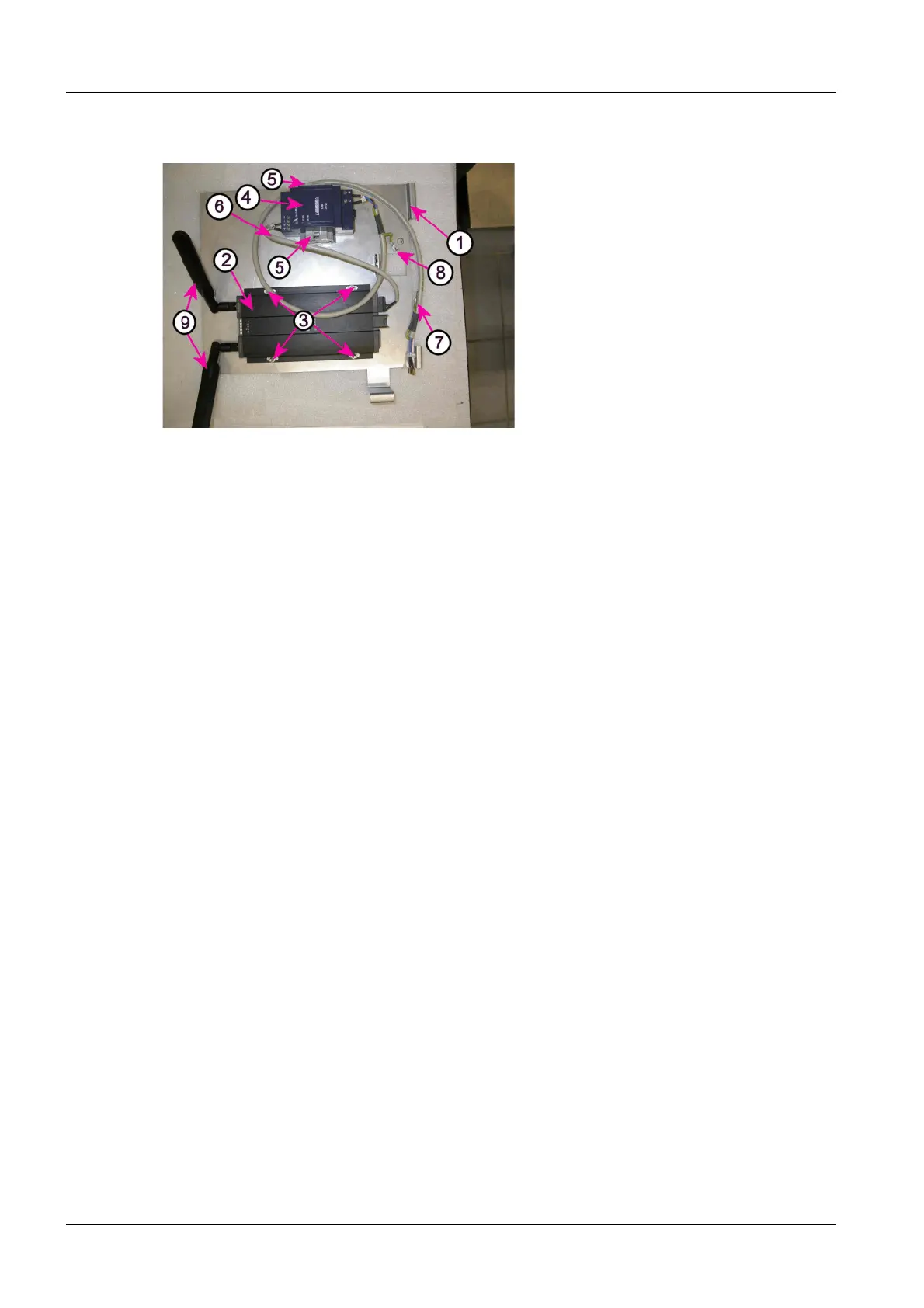
Fig. 4: WLAN Client installed on the mounting plate
Pos. 1 Mounting plate
Pos. 2 WLAN Client
Pos. 3 WLAN Client mounting points
Pos. 4 Power supply
Pos. 5 End pieces for the cap rail
Pos. 6 24V power supply connection cable - WLAN Client
Pos. 7 Power supply power cable - WLAN power switch
Pos. 8 Threaded studs for ground wire connection
Pos. 9 WLAN antennas, installed
Installing the WLAN Client
• Insert the antennas (2/Fig.3/p.13) and tighten the threads at both WLAN Client
antenna sockets (3/Fig.3/p.13).
¹ The illustration (Fig.4/p.14) shows the approximate desired location of the
antennas following installation in the monitor carriages.
• Place the WLAN Client (2/Fig.4/p.14) as shown on the threaded studs
(3/Fig.4/p.14) on the mounting plate (1/Fig.4/p.14) and secure it in place with
washers and nuts.
Installing the WLAN Power Supply
• Place the WLAN power supply (4/Fig.4/p.14) on the existing cap rail and snap it in
place.
¹ If the power supply cannot be snapped in place, slightly pull out the latching lever
on the power supply (8/Fig. 13 / p. 21) and press the power supply onto the cap
rail. Let go of the latching lever. Check for correct seating of the power supply on
the cap rail.
• Place the two end pieces (5/Fig.4/p.14) to secure the power supply on the cap rail
and secure them in place.
¹ The power supply is secured against moving sideways on the cap rail.