20 Installing the WLAN Expansion
DRAFT 22.04.2008
ARCADIS SP00-000.814.09.01.02 Siemens
11.07 CS PS SP
Page 20 of 78
Medical Solutions
Installation with the Monitor Carriage, 10143404 2.1
NOTE
Perform this section only if the monitor carriage, 10143404,
is configured.
NOTE
As a prerequisite for installation, the 2-part network connec-
tion, 10143416, must already be installed.
If this is not the case, install the 2-part network connection
according to these installation instructions prior to install-
ing the WLAN Expansion.
Overview of Required Parts 0
Removing the Cover Panels 0
• Remove the large, rear cover panel on the monitor carriage.
• Remove the small cover panel on the right (network connection panel) on the monitor
carriage.
• Remove the cover panels on the right and left sides on the monitor carriage.
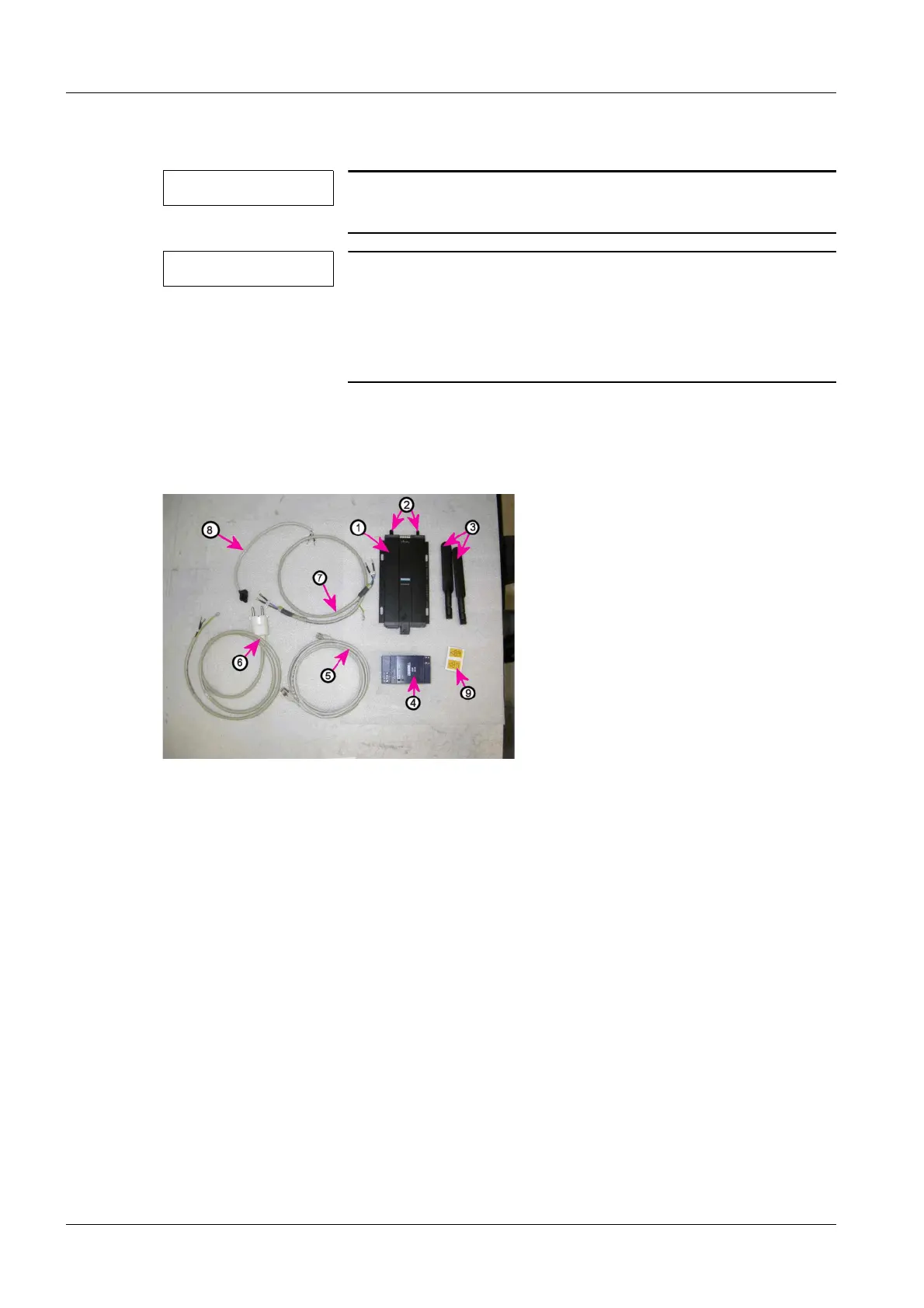
Fig. 11: WLAN electronics, cables and labels
Pos. 1 WLAN Client
Pos. 2 WLAN Client antenna sockets
Pos. 3 WLAN Client antennas
Pos. 4 WLAN power supply
Pos. 5 WLAN Client RJ45 cable - network switch
Pos. 6 WLAN power switch cable, power outlet strip
Pos. 7 WLAN power switch cable - WLAN power supply
Pos. 8 24V WLAN Client cable - WLAN power supply
Pos. 9 Label with reference to the Operator Manual
Parts not shown:
¹ WLAN power switch
¹ End pieces for the cap rail
 Loading...