EasyManuals Logo

Siemens CPU 315-2 DP Hardware And Installation Guide

Siemens CPU 315-2 DP
238 pages
To Next Page IconTo Next Page
To Previous Page IconTo Previous Page
Page #101 background imageLoading...
Page #101 background image
:LULQJ
S7-300 Automation System, Hardware and Installation: CPU 31xC and CPU 31x
A5E00105492-03
7-15
The two rows of the shielding contact element allow you install a maximum of
4 shielding terminals.
CPU
PS
1
1
22
3
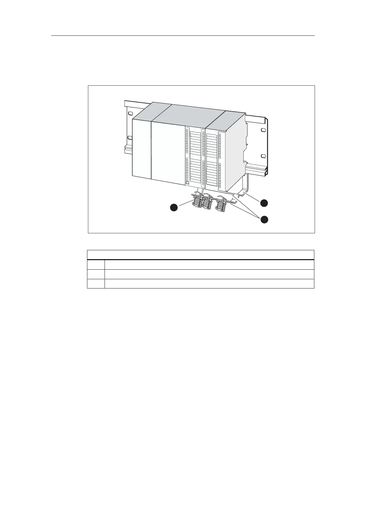
Figure 7-6 Shielding contact element underneath two signal modules
7KHGLDJUDPLOOXVWUDWHVXQGHUQXPEHU
 Bracket of shielding contact element
 Edge of bracket where the shielding terminal(s) must be placed.
 Shielding terminals
7HUPLQDWLQJFDEOHV
Only one or two shielded cables can be terminated per shielding terminal (see the
figure below). The cable is clamped in at the stripped cable shielding.
1. Strip the cable shielding to a length of at least 20 mm.
2. Clamp in the stripped cable shielding underneath the shielding contact clamp.
Push the shielding clamp towards the module (1) and feed the cable through
underneath the clamp (2).

Table of Contents

Other manuals for Siemens CPU 315-2 DP

Questions and Answers:

Question and Answer IconNeed help?

Do you have a question about the Siemens CPU 315-2 DP and is the answer not in the manual?

Siemens CPU 315-2 DP Specifications

General IconGeneral
Memory64 KB
Power Supply24 V DC
Order Number6ES7 315-2AG10-0AB0
Number of DP Masters1
Number of DP Slaves124
Load Memory64 KB
Number of Timers256
Number of Counters256
Data Memory64 KB
Operating Temperature0 to 60 °C
Integrated InterfacesMPI, DP
Digital OutputsNot integrated
Analog InputsNot integrated
Analog OutputsNot integrated
Programming LanguagesLAD, FBD, STL
Digital InputsNot integrated
Weight660 g

Related product manuals