EasyManuals Logo

Siemens CPU 315-2 DP Hardware And Installation Guide

Siemens CPU 315-2 DP
238 pages
To Next Page IconTo Next Page
To Previous Page IconTo Previous Page
Page #32 background imageLoading...
Page #32 background image
&RQILJXULQJ
S7-300 Automation System, Hardware and Installation: CPU 31xC and CPU 31x
5-6 A5E00105492-03
5HTXLUHGFOHDUDQFHV
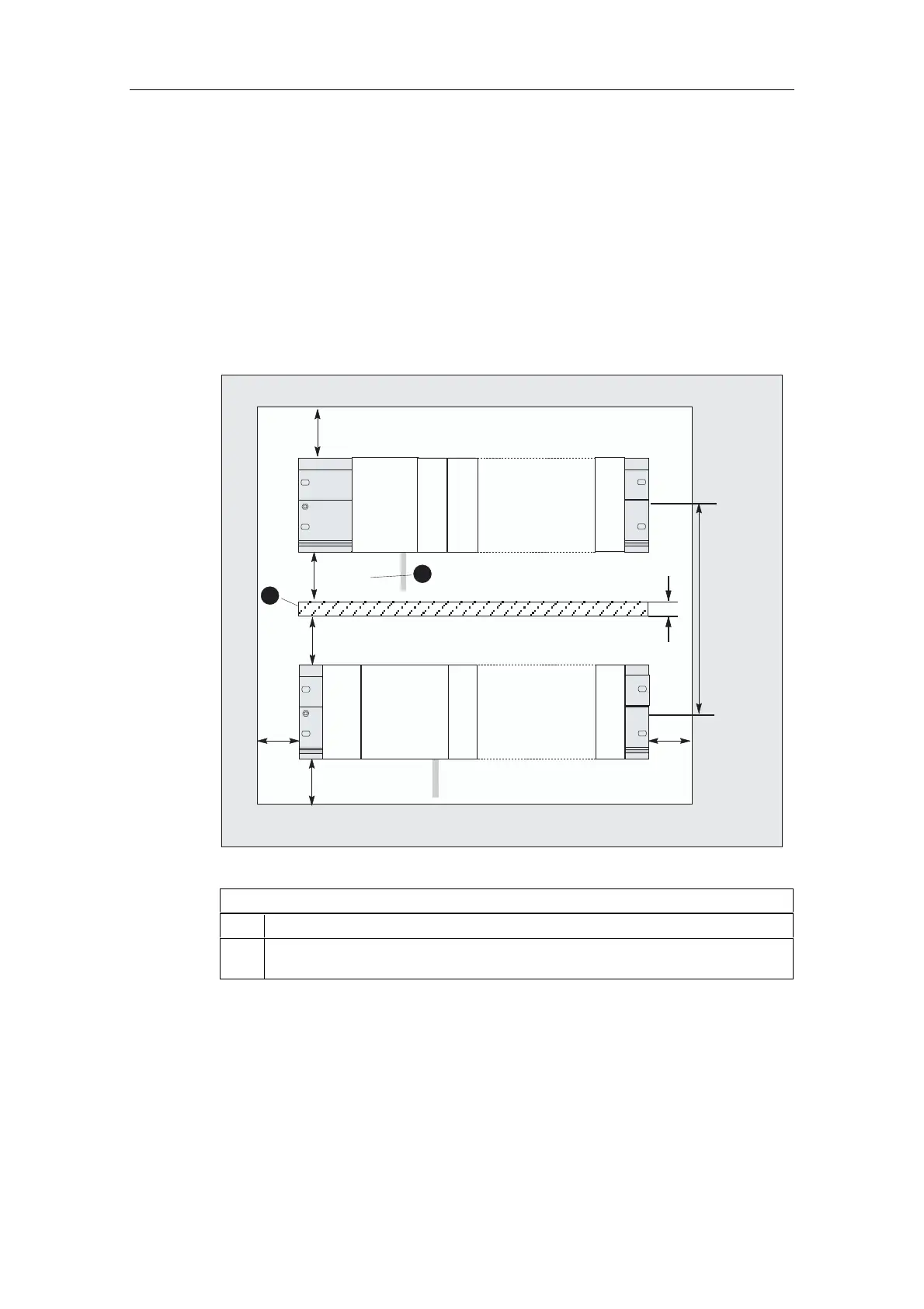
You must maintain the clearance shown in the figure in order to provide sufficient
space to install the modules and to dissipate the heat generated by the modules.
The S7-300 assembly on multiple racks shown in the figure below specifies the
clearance between racks and adjacent components, cable ducts, cabinet walls etc.
For example, if you wire your modules using a cable duct, the clearance between
the bottom edge of the shielding contact element and the cable duct must be 40
mm.
40 mm
40 mm
20 mm
40 mm
a
200 mm + a
40 mm
20 mm
PS
1
2
SM
SM
SM
SM
SM
CPU
CPU
Figure 5-3 Clearance
.H\WRQXPEHUVLQWKHILJXUH
 Wiring using a cable duct
 Clearance between cable channel and bottom edge of shielding contact element
must be 40 mm

Table of Contents

Other manuals for Siemens CPU 315-2 DP

Questions and Answers:

Question and Answer IconNeed help?

Do you have a question about the Siemens CPU 315-2 DP and is the answer not in the manual?

Siemens CPU 315-2 DP Specifications

General IconGeneral
Memory64 KB
Power Supply24 V DC
Order Number6ES7 315-2AG10-0AB0
Number of DP Masters1
Number of DP Slaves124
Load Memory64 KB
Number of Timers256
Number of Counters256
Data Memory64 KB
Operating Temperature0 to 60 °C
Integrated InterfacesMPI, DP
Digital OutputsNot integrated
Analog InputsNot integrated
Analog OutputsNot integrated
Programming LanguagesLAD, FBD, STL
Digital InputsNot integrated
Weight660 g

Related product manuals