EasyManuals Logo

Siemens CPU 315-2 DP Hardware And Installation Guide

Siemens CPU 315-2 DP
238 pages
To Next Page IconTo Next Page
To Previous Page IconTo Previous Page
Page #84 background imageLoading...
Page #84 background image
,QVWDOODWLRQ
S7-300 Automation System, Hardware and Installation: CPU 31xC and CPU 31x
6-8 A5E00105492-03
,QVWDOODWLRQVWHSV
The steps for installing the modules are described below.
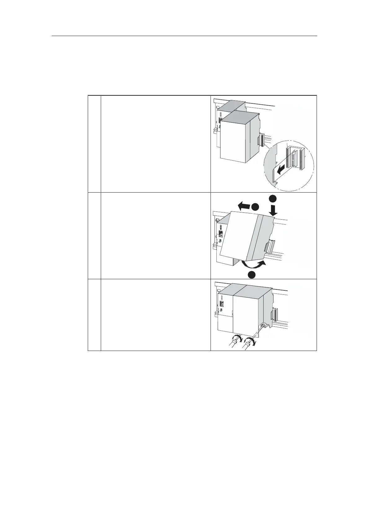
1. Plug the bus connectors into the CPU and
signal/function/communication/interface
modules.
One bus connector is included per
module, but not for the CPU.
Always start at the CPU when you plug
in the bus connectors. Here, take the
bus connector of the "last" module in
the row.
Insert the bus connectors into the
other modules.
The "last" module is not equipped with
a bus connector.
CPU
2. Lower each module onto the rail in the
intended order , slide each module in
turn to the module on the left ), and pivot
the module down into place .
CPU
2
1
3
3. Attach the modules with screws until
hand-tight.
CPU

Table of Contents

Other manuals for Siemens CPU 315-2 DP

Questions and Answers:

Question and Answer IconNeed help?

Do you have a question about the Siemens CPU 315-2 DP and is the answer not in the manual?

Siemens CPU 315-2 DP Specifications

General IconGeneral
Memory64 KB
Power Supply24 V DC
Order Number6ES7 315-2AG10-0AB0
Number of DP Masters1
Number of DP Slaves124
Load Memory64 KB
Number of Timers256
Number of Counters256
Data Memory64 KB
Operating Temperature0 to 60 °C
Integrated InterfacesMPI, DP
Digital OutputsNot integrated
Analog InputsNot integrated
Analog OutputsNot integrated
Programming LanguagesLAD, FBD, STL
Digital InputsNot integrated
Weight660 g

Related product manuals