34 / 96
BA 5030 en 02/2013
For safety reasons, it is absolutely prohibited to change the slipping torque.
After having stopped the motor, there is a danger that the load is not safely held in its
position and can run in reverse direction at high speed.
As a rule, the backstop operates without wear. As a precaution, the dimension "x
min.
" must be
checked once yearly and after every releasing operation (Type FXRT only).
The dimension “x min.” for the backstop must not be smaller than that stated on the
rating plate of the backstop. When this value ist reached, Siemens must be consulted.
To avoid damaging the backstop or the gear unit, the motor must not be run adversely
to the stop direction of the gear unit.
Observe the notice fixed to the gear unit.
If a potentially explosive atmosphere develops, the release mechanism must not be
operated (type FXRT only). If this type is used with a release device, the operating
instructions for this backstop must also be followed.
5.10 Cooling
Depending on requirements, the gear unit is fitted with a fan, a cooling coil or
a separately provided oilsupply system. In the case of a separate oilsupply system,
the specific instructions for this oilsupply system must be observed.
The oilsupply system must have been designed and manufactured for use in
accordance with Directive 94/9/EC.
When installing the gear unit free convection must be ensured on the housing surface, in order
to definitely avoid overheating the gear unit.
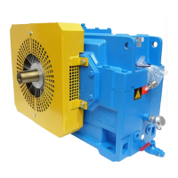
5.10.1 Fan
As a rule the fan is mounted on the highspeed shaft of the gear unit and is protected from accidental
contact by an air guide cover. The fan sucks air through the grid of the air guide cover and blows it along
the air ducts on the side of the gear housing. It thereby dissipates a certain amount of heat from the housing.
2 2
1 1
H... B...
Fig. 21: Fan on gear units types H... and B...
1 Fan 2 Air guide cover
A detailed view of the gear unit can be obtained from the drawings in the gearunit documentation.

 Loading...


