26 / 55
BA 9213 en 03/2012
6.5 Shrink disk, mechanical version
6.5.1 Fitting the shrink disk
• Before beginning installation, the hollow shaft and the stub shaft must be carefully cleaned.
Observe manufacturer’s instructions for handling lubricants and solvents.
Do not allow cleansing agent or solvent to affect surfaces with paint coating.
The bore of the hollow shaft and the stub shaft must be absolutely clean, free of grease
and oil in the area of the shrink disk seat.
This is essential for safe and reliable torque transmission.
Do not use contaminated solvents or dirty cloths nor cleansing agents containing oil
(such as paraffin or terpentine) for removing grease.
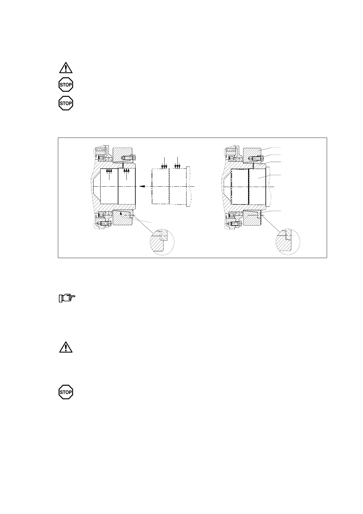
Unclamped
shrink disk
a)
Clamped
shrink disk
b)
A
B
BB
4
5
2
1
3
A Greased B Absolutely greasefree
Fig. 6: Fitting the shrink disk
1 Stub shaft 3 Inner ring 5 Tensioning bolt
2 Hollow shaft 4 Outer ring
The outer surface of the hollow shaft must be lightly greased in the area of the shrink-disk seat.
For a detailed view, refer to the dimensioned drawing in the gearunit documentation.
• Place the shrink disk on the hollow shaft and fasten, if required. For the exact installation height (W) of
the shrink disk, refer to the dimensioned drawing.
For transporting and lifting the shrink disk it may be required to use a suitable lifting
device!
Make sure that the shrink disk cannot slip off the hollow shaft.
• Fitting the stub shaft or sliding the hollow shaft onto the stub shaft
Do not tighten the tensioning bolts (5) until the stub shaft is installed too.
• Tighten the tensioning bolts (5) gradually one after the other, working round several times by quarter
turns.
 Loading...