7ML19985QD82 MultiRanger – QUICK START MANUAL Page EN-3
mmmmm
English
Installation
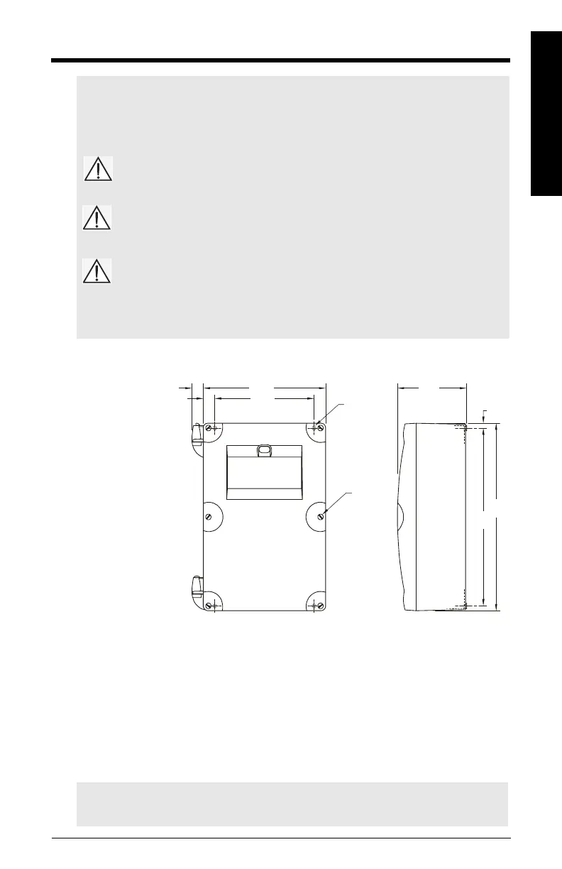
Wall Mount Installation
Notes:
• Installation shall only be performed by qualified personnel and in accordance with local
governing regulations.
• This product is susceptible to electrostatic shock. Follow proper grounding procedures.
All field wiring must have insulation suitable for at least 250 V.
Hazardous voltage present on transducer terminals during operation.
DC terminals shall be supplied from an SELV source in accordance with
IEC 1010-1 Annex H.
• The non-metallic enclosure does not provide grounding between conduit connections. Use
grounding type bushings and jumpers.
Note: For conduit locations and assembly for mounting in Class 1, Div. 2 applications,
please see Drawing 23650314 in Appendix A.
160.3mm
(6.325")
130mm
(5.125")
91mm
(3.58")
6.6mm
(0.26")
240m
(9.45")
227mm
(8.93")
4.3mm Dia.
(0.17")
Four Mounting
Holes
Enclosure
Screws (6)
1. Remove the lid
screws and open
the lid to reveal the
mounting screw
holes.
2. Mark and drill four
holes in the
mounting surface for
the screws.
(customer supplied).
3. Fasten with a long
screwdriver.
15.2mm
(0.6")
14.9mm
(0.58")
Cable Entry Locations
Conduit Cable Entry
1. Remove screws holding motherboard and
pull straight out.
2. Drill cable entry holes carefully, leaving
room for existing contents.
3. Attach conduits using approved suitably
sized hubs for watertight application.
Exposed Cable Entry (supplied glands)
1. Unscrew glands and attach loosely to
enclosure.
2. Thread cables through glands. Keep power
cable separate from signal cable.
3. Wire cables to terminal blocks and tighten
glands to form a good seal.