IP Adapter Nur für den internen Gebrauch
P31003-E8400-A100-3-7620
7-4 Service Manual
Connection to the System
7.3 Connection to the System
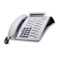
Figure 7-3 Overview: connecting an optiPoint IPadapter to the system
Connect the optiPoint IPadapter to the Hicom system in the following sequence (please also
note the diagram "Electrical connection of the optiPoint IPadapter"):
1. First of all, connect the U
P0/E
port of the IPadapter to the Hicom system (SLMO board).
Use the cable supplied with RJ-11 Mini-Western connectors (point 1).
2. Connect the IPadapter to the LAN network. Use the LAN network cable (max. 3 m) sup-
plied for this (cable features 3 RJ-45 Mini-Western connector (point 2)).
The optiPoint IPadapter can be operated as a desktop unit or can be mounted on the wall with
a screw. The wall attachment can be found on the back of the IPadapter (point 3).
Figure 7-4 Electrical connection of the optiPoint IPadapter
PIN assignments on the IPadapter
Connector/ jack Pin 1 Pin 2 Pin 3 Pin 4 Pin 5 Pin 6 Pin 7 Pin 8
U
P0/E
RJ11 NC DC- a(U
P0/E
)b(U
P0/E
) DC+ NC
LAN RJ 45 TDX+ TCD- RXD+ NC NC RXD: NC NC
Table 7-1 Pin assignment
12
Hicom/
HiPath
(SLMO
board)
LAN - I/F
10 Base T
U
P0/E
optiPoint
IPadapter
1
2
3
 Loading...