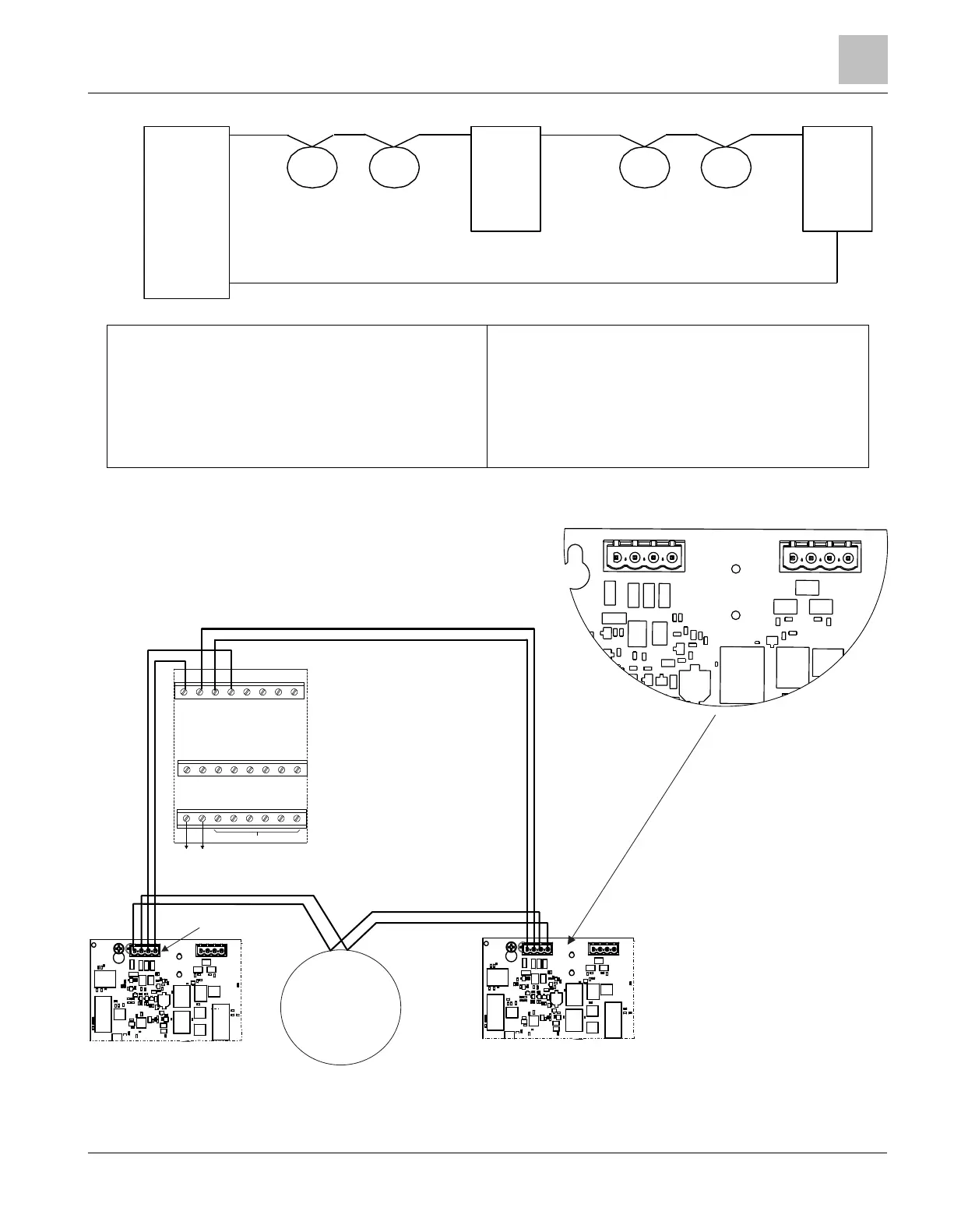
EasyManuals Logo

Siemens PAD-5 Series User Manual

Siemens PAD-5 Series
40 pages
To Next Page IconTo Next Page
To Previous Page IconTo Previous Page
Page #31 background imageLoading...
Page #31 background image
Model PAD-5
1
Wiring and Configuring the PAD-5-MB
Siemens Industry, Inc.
A6V101030358_en--_c
Smart Infrastructure
Figure 13: Class A Wiring
CLASS A Topology
(Mixed Mode polarity insensitive and isolator
devices)
High Level Connection Diagram showing PAD-5-MB
as an Isolator device on XDLC loop
Siemens SLC Devices include polarity insensitive
Dets, TRIs, Pull Stations, Call Points, Conventional
Zone Modules, etc.
A maximum of 30 SLCs can be connected
between PAD-5s, or any other isolating devices
in the Class A loop.
PAD-5 is a polarity sensitive and isolating device.
XDLC
SLC
Device
SLC
Device
PAD-5
SLC
Device
SLC
Device
PAD-5
XDLC Card
PAD-5
PAD-5
5 6 7 8
13 14 15 16
ONE SLOT OF CC -5
21 22 23 24
TO 24VDC FROM THE PSC-12
DO NOT USE
+ +
- -
+ + - -
1 2 3 4
9 10 11 12
17 18 19 20
24V+ 24V-
+
-
+
-
+ -+ -
SLC
Device
1
X700
4
1 4
-
+
6
1
b
+
1
b
+
5
B
F
+
BF-
B
E
L
L
F
O
L
L
O
W
E
R
X700
X600
BF-
B
F
+
P2

Questions and Answers:

Question and Answer IconNeed help?

Do you have a question about the Siemens PAD-5 Series and is the answer not in the manual?

Siemens PAD-5 Series Specifications

General IconGeneral
BrandSiemens
ModelPAD-5 Series
CategoryComputer Hardware
LanguageEnglish

Related product manuals