Description
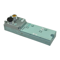
RF180C communication module
10 Operating Instructions, 12/2012, J31069-D0177-U001-A6-7618
Potential
Ungrounded installation of the system is possible with the RF180C. The following circuit
shows the internal relationships of the reference potentials.
9'&VXSSO\
5)&DQGUHDGHU
,QWHUQDOVXSSO\
UHDGHULQWHUIDFH
352),1(7,2
X[LOLDU\YROWDJHIRU
EXVFRQQHFWLRQ
6KLHOG
0˖
0˖
0˖
Q)
Q)
Q)
Q)
0
0
0
Figure 2-2 Galvanic isolation of RF180C
Integration
The following figure shows how the RF180C with M12 connection block (7/8") is integrated in
an automation system. The push-pull connection block is integrated in the same manner as
the M12 connection block (7/8").
Controller e.g.
CPU S7-400
Reader
Transponder
to other
PROFINET nodes
24 VDC
RF180C
PROFINET
X1
X2
Figure 2-3 RF180C configurator with M12 connection block (7/8")
The RF180C is integrated into the hardware configuration by means of a GSDML file. The
RF180C can then be configured using HW Config of the SIMATIC manager or another
PROFINET tool. You will find the GSDML file on the
"RFID Systems Software &
Documentation (http://support.automation.siemens.com/WW/view/
en/65102624)" DVD.