Introduction
1.2Description
• Conformal coated printed circuit boards (optional)
1.2 Description
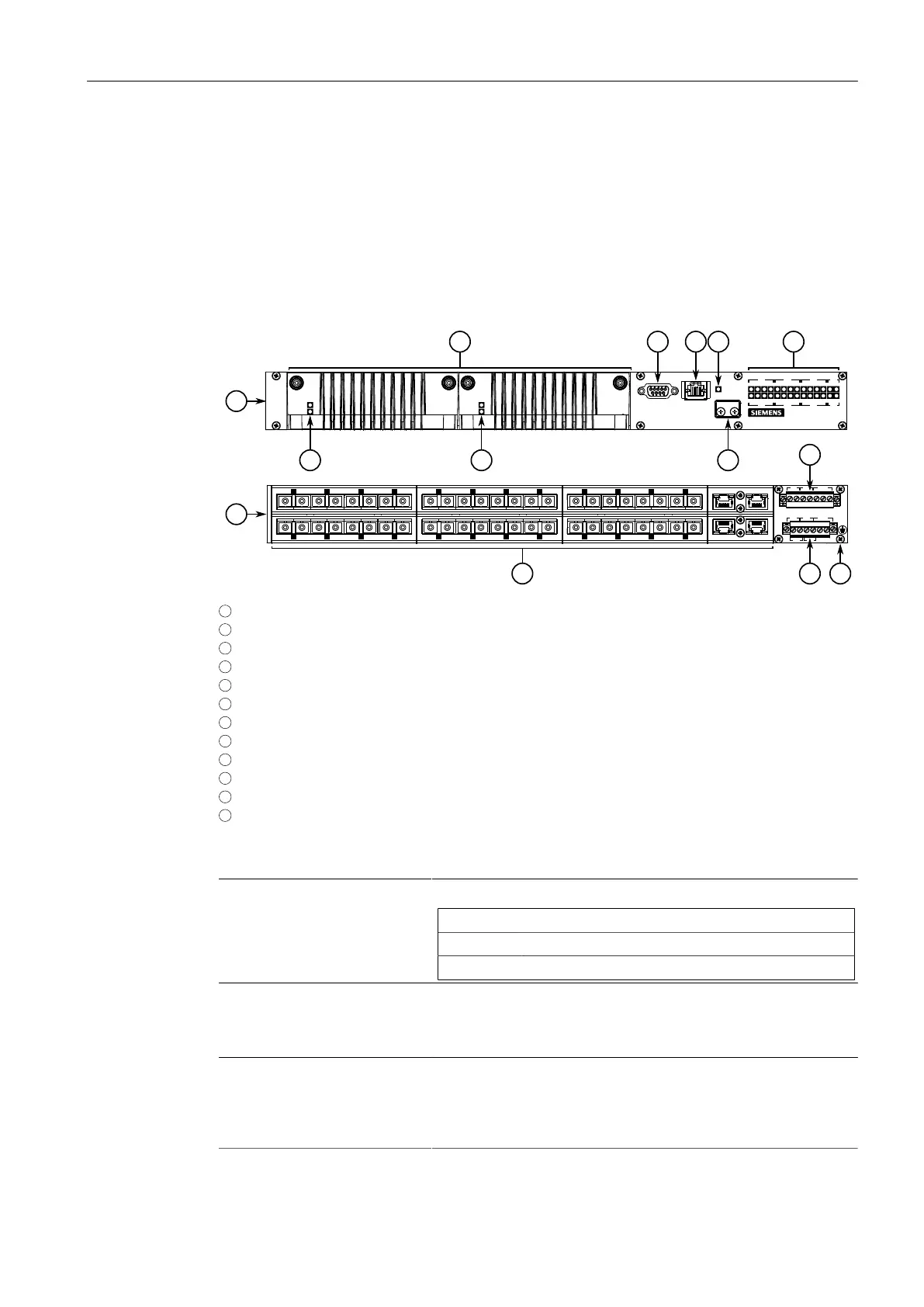
The RUGGEDCOM RSG2488 features various ports, controls and indicator LEDs on the
front panel for connecting, configuring and troubleshooting the device.
1
Front
2
Rear
3
Power Modules
4
Power Status LEDs
5
RS-232 Serial Console Port (DB9)
6
Management Port
7
Alarm Indicator LED
8
Access Plate
9
Port Status LEDs
10
Line Modules
11
Power Supply Terminal Block
12
Chassis Ground Terminal
Figure1.1 RUGGEDCOM RSG2488
Power Status LEDs Indicates the status of the power modules.
LED Description
I The power module is receiving power
O The power module is supplying power
RS-232 Console Port The serial console port is for interfacing directly with the device
and accessing initial management functions. For information
about connecting to the device via the serial console port, refer to
"Connecting to the Device (Page 21)".
Management Port The 10/100Base-T Ethernet management port is for system
management that is out-of-band from the switch fabric. For
information about connecting to the device via the 10/100Base-
T Ethernet management port, refer to "Connecting to the Device
(Page 21)".
2
RUGGEDCOM RSG2488
Installation Manual, 07/2021, C79000-G8976-1048-11

 Loading...


