Technical specifications
6.7 Technical specifications for terminal modules
SIMATIC TOP connect for S7-1500 and ET200MP
64 Manual,
Table 6- 16 Technical specifications for terminal module TPOo
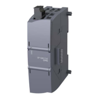
Terminal module TPOo optocoupler for outputs
6ES7924-0BF20-0Bx0
Input data for supply voltage
Potential connection (L1/M1)
24 V DC (20.4 ... 28.8 V DC)
Input data for switching inputs
Number of switching inputs 8 channels (channel 0 ... 7)
With reverse polarity protection
24 V DC (15 ... 28.8 V DC)
min. 5 mA with 20 V DC, per channel
Output data for supply voltage
op
24 V DC (20 ... 30 V DC), one per group of 4
op
with conditional reverse polarity protection
Up to 30 V DC
(Protected against reverse polarity if the ground
potential of the output load is directly connected
to the 0 V supply of the power supply unit.)
Current consumption Approx. 10 mA at 24 V DC + output currents
8 channels (channel 0 ... 7)
Short-circuit protection When Vop < 24 V DC or
20 … 30 V DC/max. 20 A
No continuous short-circuit protection, max.
op
max. 40 W at 24 V per channel
Clocked output signal (approx. 2 ... 20 ms)
Typ. 100 ɥs / 250 ɥs with resistive load
Switching frequency max. 500 Hz with 4 A resistive load (square wave
voltage, pulse/pause 1:1)
"Overload" fault display Red LED per channel, in the event of wire break
or short-circuit
Wire break display active
load
Recommended conductor cross-section for cable 1.5 mm
2
Group fault messages SF1, SF2
Monitored channels

 Loading...


