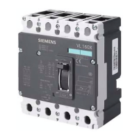
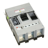
Insulating measure Article No. contained in
E 3VW9723-0WF30
3VW9724-0WF40
3VW9011-0AL71
3VW9011-0AL72
F 3VW9011-0AL71
3VW9011-0AL72
3VW9011-0AL73
3VW9011-0AL74
3VW9011-0AL77
3VW9011-0AL78
Busbar isolation
Note
The distance specications for busbar isolation apply to the 3VA27 molded case circuit breaker.
3VA27 A
≤ 415 VAC 250 mm
[9.84 in]
> 415 VAC 400 mm
[15.75 in]
4.2.3 Armature plates
The electrodynamic forces that arise during a short-circuit can result in high mechanical loads in
and on the switchboard. To minimize the eects, armature plates must be mounted in the
vicinity of the terminals of the circuit breaker.
Busbars
The following diagram shows the distance of the rst armature plate depending on the
prospective short-circuit current when busbars are used:
Application planning
4.2Power supply, grounding, and connection
3VA27 molded case circuit breakers & 3WL10 air circuit breakers
Equipment Manual, 10/2023, L1V30499596002-03 149

 Loading...


