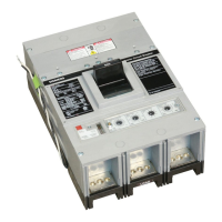
The following table describes the general testing of the circuit breaker and its installed
environment:
Items to be tested
1)
Checks
Switchboard 1. Sucient ventilation to avoid overtemperatures
2. Clean installation location, free of all installation waste (e.g. cables,
tools, metal splinters)
3. Circuit breaker correctly mounted (tightening torques and ventilation
clearances observed)
4. The ambient conditions of the installation must match the specica‐
tions (see Chapter Application planning (Page129)).
Connections 1. Electrical connections at the terminals of the circuit breaker tightened
2. Cables, busbars, and auxiliary current wiring have sucient conductor
cross-sections
3. Required insulation clearances between the phases (if necessary with
phase barriers) and from phases to the switchboard panel.
Operations Perform a few open and close operations.
It must be possible to operate the lever of the operator normally and to
charge the stored energy mechanism.
Note: If an undervoltage coil is present, the circuit breaker can only be
closed when a voltage is applied at the corresponding auxiliary conduc‐
tor terminals.
1)
If present
The following tests must be conducted for inspection before re-commissioning after tripping
and after lengthy storage under certain ambient conditions. These can be performed with
a TD310 test device to power the ETU. They are not mandatory for a device from the
factory because the circuit breaker is completely and thoroughly tested, including all installed
accessories, before delivery. A trip test conrms correct mechanical functioning of the
tripping plunger on the trip solenoid, actuated by the ETU. Electronic monitoring of the
entire connection between the current transformers, ETU, and trip solenoid is performed
continuously by the electronics itself (watchdog).
Items to be tested
1)
Checks
Enable alarms Connect the ETU to a test device and check that no alarms are present.
Status of the circuit breaker
On the ETUs of the 3-series, the status of the circuit breaker must not be
incorrect (see tables of the LED display in Chapter Alarms (Page191)).
Perform a close/open operation on the circuit breaker and check that no
alarms have occurred.
On the ETUs of the 6-series, the status of the circuit breaker must be
correctly shown on the display. Perform a close/open operation on the
circuit breaker and check that the change in circuit breaker status is cor‐
rectly displayed.
Trip test Make a trip attempt with the circuit breaker closed during an idle period
(without circulating currents of the mains connection) and check that
the circuit breaker opens.
1)
If present
Connection and commissioning
5.5Commissioning
3VA27 molded case circuit breakers & 3WL10 air circuit breakers
Equipment Manual, 10/2023, L1V30499596002-03 179

 Loading...


