Assembly
SICAM TM, Installation 37
DC6-015-2.04, Edition 10.2014
3.7. Installing TM Modules
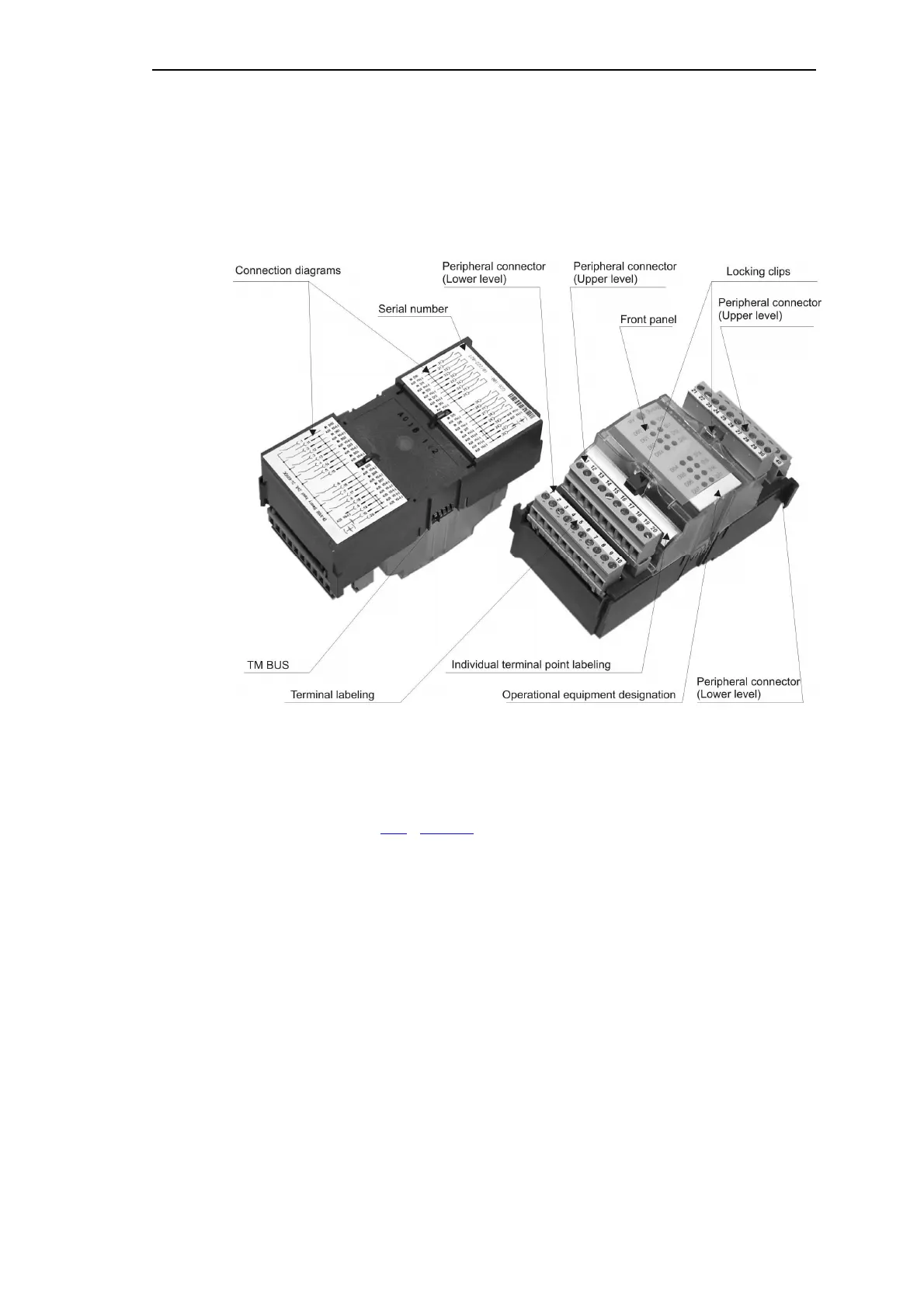
3.7.1. Design and Elements of a Module
Peripheral connector
On the modules there are, depending on the type, up to 4 10-pole male connectors with
removable screw terminals. (Optionally spring-loaded- or crimp terminals can be used.)
With the screw terminal, as an option there exists the possibility of a mechanical terminal
coding (refer to chapter 11.6
; "Terminal Coding").
Connection Diagrams
These are located on the underside of the modules. They indicate examples of the external
circuitry of the modules.

 Loading...