Assembly
38 SICAM TM, Installation
Edition 10.2014, DC6-015-2.04
Locking Clips
By means of these two metal clips the modules are locked onto the TS-35-rail and also
removed.
Display Elements / Front Panel
The number and meaning of the displays on the front panel are, apart from the RY-LED,
different on all modules. While the RY-LED always displays the functional readiness of the
module, the meaning of the other displays is to be taken from the respective description
(SICAM TM I/O Modules).
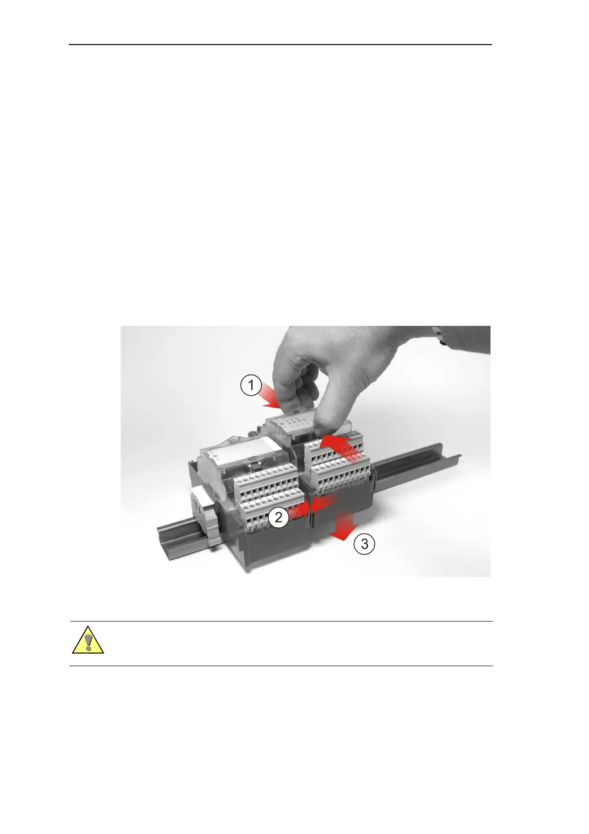
3.7.2. Handling
The modules can be installed on the TS35 rail and removed again by hand, without any tools.
For this, the locking clips on the top side of the module are pressed together , the module
coupled with the neighboring module by means of the guides at the corners of the housing
and positioned on the TS35 rail .
For the removal, the locking clips are again pressed together and the module withdrawn with
clips pressed together.
Warning
The connecting and withdrawal of modules is only permitted in a de-energized state. This state is
achieved by interrupting the power supply to the power supply unit and to the peripherals.

 Loading...